Vanguard TRM-20_40 User Manual
Page 34
TRM-20 AND TRM-40 USER’S MANUAL
REV 1
30
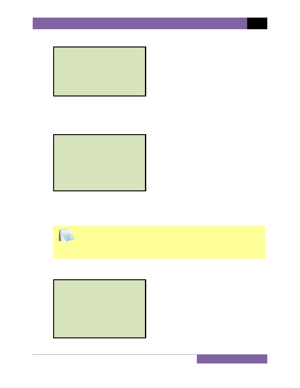
After the TRM finishes its internal calibration, the following screen will be displayed:
This is only an informational screen to remind the operator that a test is in progress. The
display duration of this message depends on the size of the winding’s inductance.
l. The TRM determines when the resistance reading is stable and displays the resistance
values on the LCD screen as shown below:
The TRM will continue the test and update the resistance values on the LCD screen.
While the test is in progress, you can press the
[ENTER]
key to save the current
readings from the LCD screen to the TRM’s internal working memory. You can store up
to 99 readings per test.
NOTE
Although this process can be used to store multiple readings when testing a
Load Tap Changer (LTC) or Voltage Regulator, a more convenient method is
also available. Please see section 3.10 for information about performing an
LTC or Voltage Regulator test.
If the
[ENTER]
key is pressed, the data is saved and the following screen will be
displayed on the LCD screen:
TEST IN PROGRESS 14
===
>
SAVING TEST
<
===
I = 10.01 AMPS
R1 = 1.465
m
Ω
R2 = 1.448
m
Ω
** XFMR ENERGIZED! **
TEST IN PROGRESS 14
I = 10.01 AMPS
R1 = 1.465
m
Ω
R2 = 1.448
m
Ω
*XFMR CHARGING*
please wait...
** XFMR ENERGIZED! **