5 summit z2-16 rear panel description – Teledyne LeCroy Summit Z2-16 PCI Express Multi-lane Exerciser User Manual User Manual
Page 15
Summit Z2-16 Exerciser User Manual
Chapter 2: Hardware Description
Teledyne LeCroy
11
2.5 Summit Z2-16 Rear Panel Description
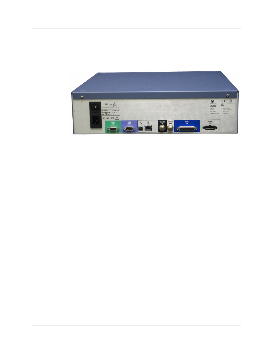
From left to right, the Summit Z2-16 rear panel contains the following components:
Figure 2.2 Summit Z2-16 Rear Panel
Wide-range AC Connector Module
•
Power on/off switch
•
Enclosed 5x20 mm 2.0A 250 V fast acting glass fuse
•
Power socket
Warning! For continued protection against fire, replace fuse only with the type and
rating specified above.
Sync In and Sync Out Connectors
(not currently active) These connectors allow multiple Summit T2-16 or Summit Z2-16
analyzers to send synchronization and control messages to one another.
USB Type B Host Machine Connector
This connector links an Analyzer to the host machine for the purpose of transmitting
commands from the host machine to the Analyzer and uploading traces from the
Analyzer’s recording memory to the PETracer software for viewing and analysis.
This connector links an Exerciser to the host machine for the purpose of downloading
scripts and controlling the behavior of the Exerciser. Note: For each Analyzer or
Exerciser, use either USB or Ethernet, not both.
Ethernet Port
GIGE Connectivity allows connection to an Ethernet network and sharing of
Analyzer/Exerciser resources by multiple engineers. Note: For each Analyzer or
Exerciser, use either USB or Ethernet, not both.
BNC Connectors Trigger In and Trigger Out
These BNC connectors allow the Analyzer to transmit or receive trigger event signals.
Trigger In can receive a signal from another device and use that signal to trigger the
recording. Conversely, the Trigger Out connector can send an output signal from the
Analyzer to another device.