3 ptz camera / automation system connections, Power – Staub Electronics WPS-300-DVR-16CH WIREPATH - 16 CHANNEL DVR WITH 1TB HDD User Manual
Page 13
13
WPS-300-DVR-9CH & 16CH Installation and Users Manual
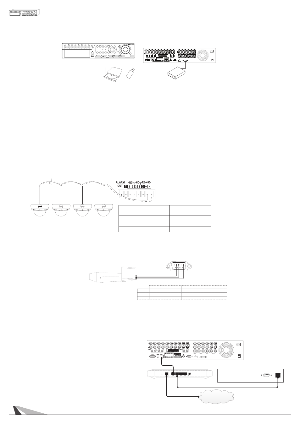
• USB 2.0 AND ESATA
Connect external storage devices such as USB thumb drives, DVD+RW drives or ESATA hard drives for
archiving video and audio.
• CAMERA LOOP OUTPUTS
Connect the BNC loop outputs to a dedicated local display (Sometimes referred to as Spot Monitors),
video distribution system, or Automation system touch panel.
• CALL-AUX OUTPUT
Connect the BNC Call-Aux output to Call-Aux input on additional DVRs when daisy chained.
• MAIN-AUX OUTPUT
Used to daisy-chain multiple DVR Monitor Outputs. MAIN-AUX OUT has the same output as MAIN OUT,
but can be switched to MAIN AUX Input through RS-485 keyboard control.
3.2.3 PTZ CAMERA / AUTOMATION SYSTEM CONNECTIONS
• PTZ CAMERAS
Connect the RS-485 connector to PTZ camera(s) via an appropriate cable. The system supports a variety
of PTZ cameras and the OSD menu of Wirepath™ Surveillance cameras. Different PTZ cameras can coexist
in a system only if they support the same protocol and baud rate. Make sure to set unique PTZ IDs to the
cameras, the DVR and any other PTZ device. Setup each camera (Section 6.1), and RS485 (Section 6.9)
accordingly.
• AUTOMATION SYSTEMS
Connect the RS232 DSUB connector to a control port on an Automation System to control the DVR. Please
refer to Section 6.9 for setup and the control protocol document found on the SnapAV Website.
*Communication PIN functionality can vary; refer to the manual for your Automation System for proper PIN functionality.
IP Control Connections
Wirepath™ DVRs provide integration with Automation Systems via Ethernet allowing for control and streaming of video.
Connect the Ethernet port to a home automation network.
For PTZ Devices
For Wirepath
Surveilance Cameras
RS485 +
RxD + (Data +)
Positive +
RS485 -
RxD + (Data -)
Negative -
GND
GND
No Connection
VGA
HDMI
ESATA
ALARM
OUT
G
G
G
G
-
+
G
RS-485
C
DC12V
POWER
External ESATA
Hard Disk Drive
Thumb Drive
DVD+RW
OR
Automation System
2 3
5
DVR RS232 DSUB
Male Connection
RS232 DSUB Connector Pin Out
300 Series DVR
Automation System*
Pin 2
TxD (Data Transmit)
Data Receive
Pin 3
RxD (Data Receive)
Data Transmit
Pin 5
GND
GND
*Communication PIN functionality can vary, refer to the Automation System manual for proper PIN
functionality.
VGA
HDM I
ESATA
ALARM
OUT
G
G
G
G
-
+
G
RS-485
C
DC12V
POWER
WPS-300 Series DVR
RS-232
Network
Control System
Router
Internet
Note: This feature is only available on DVRs with
software versions 7.77.53 or higher and requires the
home automation system manufacturer to provide the
driver. Update the DVR to the latest version available
on the SnapAV Website to use this feature.