Figure 10, Figure 11 – Staub Electronics SM-RAZOR-T-XL STRONG - LARGE RAZOR TILT MOUNT FOR 55-80 IN. FLAT-PANEL TVS User Manual
Page 9
© 2013 Strong
TM
pg.9
SM-RAZOR-T Installation Manual
Wire Management Kickstands
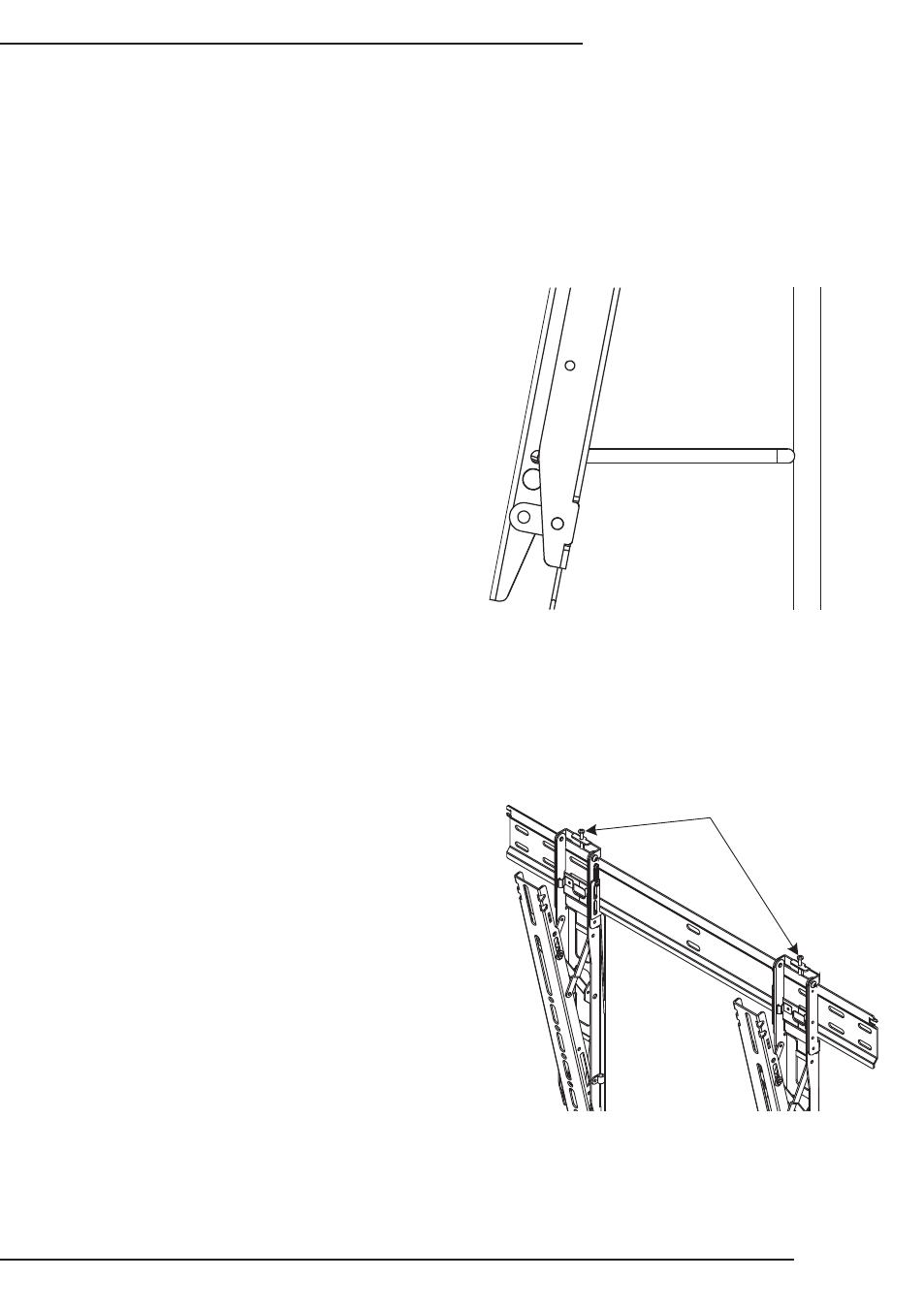
Display Leveling Adjustment
The SM-RAZOR-T mounts are equipped with a kickstand that provides space between
the display and the wall for connecting or disconnecting cabling
After mounting, the display may not be
hanging perfectly level. The set screw
at the top of each mounting hook allows
either side to be adjusted using a Phillips
screwdriver (Figure 11).
Place a level on one side of the display
as the adjustment is made. Turn the
screw clockwise to raise a side, or
counterclockwise to lower a side, until the
display is level.
Warning: Turning the leveling adjustment screws
too far clockwise to raise the display height could
lock the display brackets to the wall plate. This
could cause damage to the display or the mount
when trying to disconnect the display brackets from
the wall plate.
Note: These kickstands are provided for servicing only, it is recommended that they are
collapsed and the brackets are locked during normal placement.
A. Pull down on the rings at the
bottom of the brackets to release
them from the wall bracket.
B. Pull the kickstands out on each
bracket so that they rest on the
wall. (Figure 10)
C. When finished, collapse the
kickstands to allow the brackets
to lock onto the wall bracket.
D. Let the release strings slide
back up, and check to see that
the catches engage by gently
pulling the bottom of the display.
Figure 10
Leveling
Adjustment Screws
Figure 11