Figure 6, Figure 7 – Staub Electronics SM-RAZOR-T-XL STRONG - LARGE RAZOR TILT MOUNT FOR 55-80 IN. FLAT-PANEL TVS User Manual
Page 7
© 2013 Strong
TM
pg.7
SM-RAZOR-T Installation Manual
The wall plate is fastened to a concrete wall using the included lag screws (A) and
wall anchors (B). Be sure to use the correct number of screws and anchors to fasten
your mount as listed below:
• Verify that you have a minimum of 1-3/8” of concrete thickness to be used for
the concrete anchors.
• Do not drill into mortar joints! Be sure to mount in a solid part of the block,
generally 1”minimum from the side of the block.
• Cinder block must meet ASTM C-90 specifications.
• To avoid breaking out the back of the hole when entering a void or cavity, it is
suggested that a standard electric drill on slow setting is used to drill the hole
instead of a hammer drill.
• Concrete must be 2000 psi density minimum. Lighter density concrete may
not hold anchors.
• Make sure that the supporting surface will safely support the combined load
of the equipment and all attached hardware and components.
Mounting on a Concrete Wall
Warning: When installing wall bracket on cinder block:
Model:
SM-RAZOR-T-M:
SM-RAZOR-T-L:
SM-RAZOR-T-XL:
Number of Lag Screws:
4 (Figure 4)
6 (Figure 5)
6 (Figure 5)
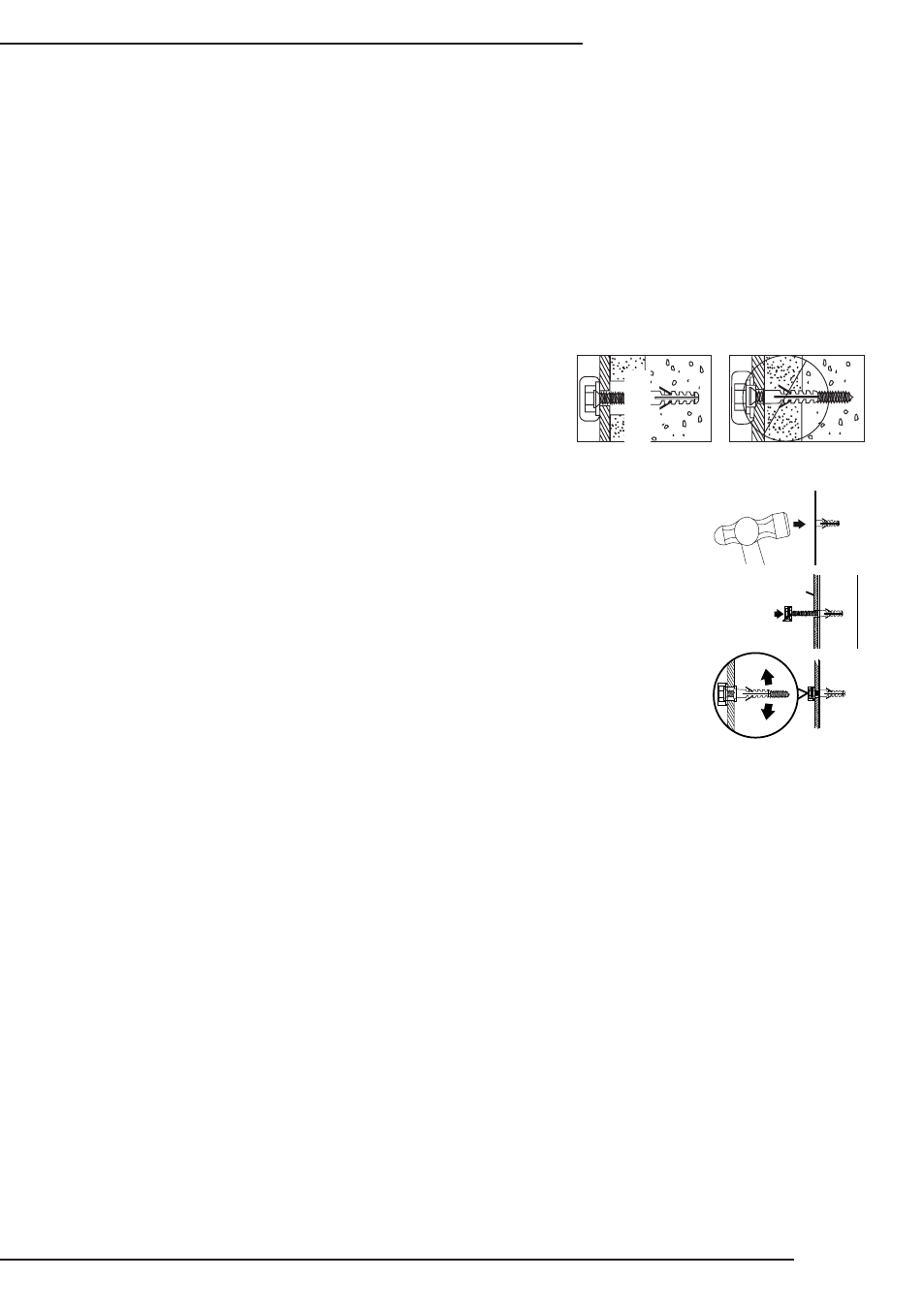
A. Pre-drill holes into concrete using 5/16”
drill bits to a depth of 2 1/2”. Insert
concrete wall anchors (B) and tap in with
hammer if necessary (Figures 6 & 7).
B. Insert the lag screws (A) into the wall
anchors (B) through the wall plate and
tighten all bolts so that wall plate is
firmly attached, but do not over tighten.
Warning:
Over tightening can damage the
bolts, greatly reducing their holding strength.
Correct
concrete
concrete
plaster/
drywall
plaster/
drywall
Incorrect
Cu
ta
w
ay
V
ie
w
Figure 2
Figure 6
Figure 6
Cutaway V
iew
Incorrect
Correct
Drill holes and
insert anchors.
Place wall arm
assembly plate
over anchor and
secure with lag screw.
Tighten all
lag screws.
Concrete
Wall
Wall Arm
Flange Bolt
Figure 7
Figure 4