Installation, Step 1. pre-drill wall for mounting, Figure 1 figure 2 – Staub Electronics SM-RAZOR-T-XL STRONG - LARGE RAZOR TILT MOUNT FOR 55-80 IN. FLAT-PANEL TVS User Manual
Page 4
SM-RAZOR-T Installation Manual
pg.4
www.snapav.com Support: 866.838.5052
Installation
Step 1. Pre-Drill Wall for Mounting
A.
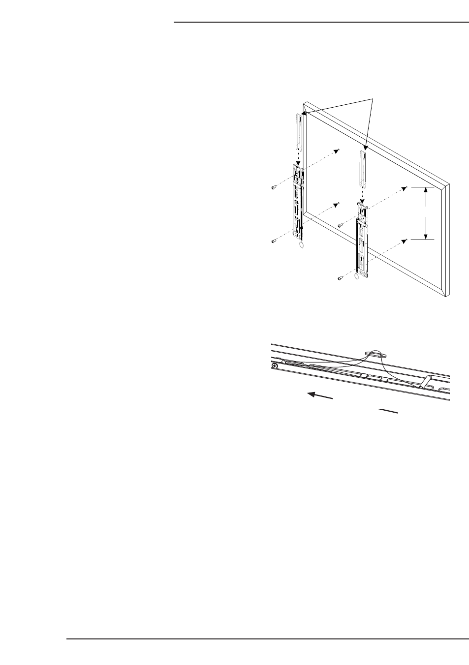
XL Model only: If the vertical VESA
pattern dimension on the display
is greater than 400 mm (Figure 1,
Dimension A), attach the extension
brackets to the tops of the display
brackets using the 8 included
screws (U) so the brackets will reach
between the VESA mounting holes
on the display.
B. Determine the diameter of the screw
(parts C through P) your display
requires by carefully trying to hand-
thread one screw into the threaded
insert on the rear of the display.
If there is any resistance, stop
immediately.
C. Spacers are commonly needed
on displays with curved backs or
recessed screw inserts. The screw
will thread through the appropriate
washer (Q or R), the display
brackets, any spacer needed (S or
T), and then into the display.
D. Mount the brackets so that they are as close to centered (vertically) on
the back of the display as possible. The pull rings and catch hooks face
inward when mounted (Figure 1). The brackets are labeled “L” and “R” for
reference.
E. Ensure the brackets are installed with the flat side to the display and are
square to each other after all screws have been installed (Figure 1).
F. Adjust the height of the bracket release string to be above the bottom of
the display (Figure 2). Slide the clip up to lengthen and down to shorten
the release string.
Figure 1
A
XL Model Only
Figure 1
Figure 2
Lengthen
Shorten
Top of Arm
XL Model Only