Securitron iEXD-24 User Manual
Page 9
PN#
500-18900
Page
9
Rev. D, 10/07
4.3 MAINTAINED BYPASS
“Maintained Bypass” means releasing the door for an extended period of time for free
exit. The most common example of this is a situation where the door is released during working
hours and put into delayed exit mode at night and during the weekends. This can be done, for
example, from a manual, alternate action switch or from a timer like Securitron’s model DT-7.
To understand implementation of an alternate action switch, you need to understand precisely
how the Bypass input functions on the control board. In the normal condition, there is no
connection between terminal BP and +V. When these terminals are connected (by a switch
closure), the door goes into Bypass and stays in that condition for as long as the terminals are
connected. When the connection is opened, the door stays in Bypass for an additional five
seconds. Therefore an alternate action switch can place the door into Bypass for an extended
period of time (all day, for example) and a momentary switch appears to put the door into
Bypass for only five seconds because the amount of time that the momentary switch is closed is
very short.
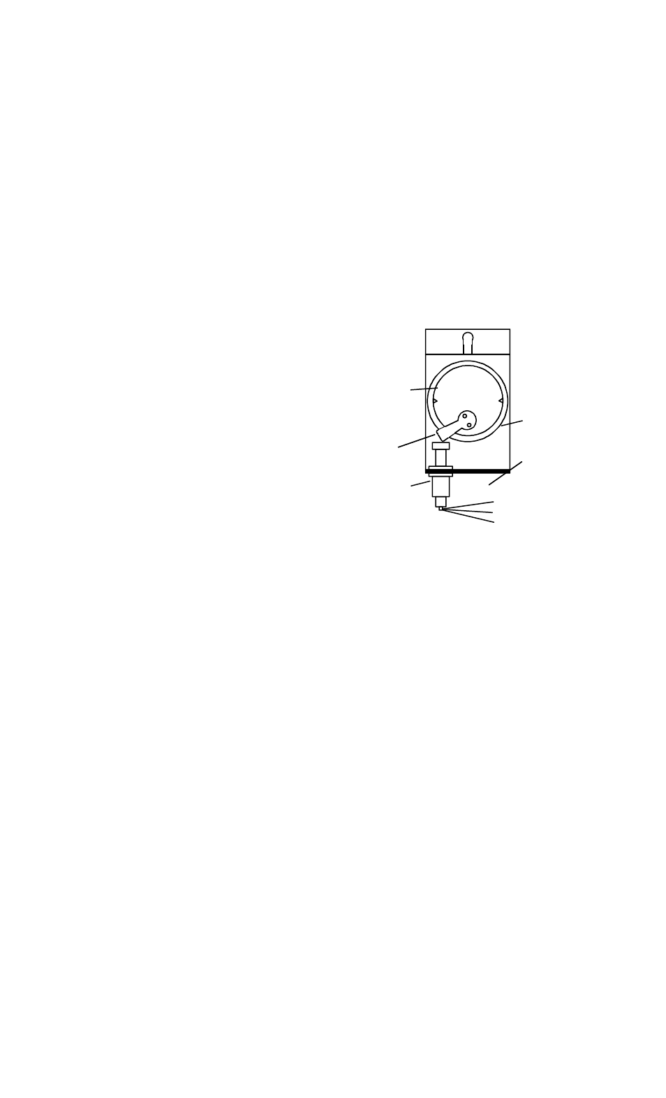
4.3.1. MAINTAINED BYPASS VIA THE INTEGRAL KEYSWITCH
A particularly convenient way to implement
manual, maintained Bypass is to upgrade the
integral keyswitch by adding a second
switch. As delivered, the back bracket of the
keyswitch mounts a single, momentary switch
which operates both the Bypass and Relocking
inputs on the control board (when the system is
secure, turning the key yields the bypass
function; when it is released following delayed
exit, turning the key yields the relocking
function). Securitron can supply a second,
alternate action (push on/push off) switch (part
number MKSA). As the drawing to the right
shows, the second switch mounts on the
opposite side from the first. The white (Com) wire of the second switch connects to +V on the
control board while either of the other wires connects to terminal BP. The operator is then
instructed that turning the key in the momentary direction (clockwise) respectively yields five
second Bypass and relocking but that when turned in the opposite direction, one click will put
the door into maintained Bypass and a second turn in that direction will restore it to normal
function.
4.4 ALARM CONTACTS
SPDT dry contacts are available on the control board (see Figure 4). When the unit is powered,
the normal (non-alarm) condition of these contacts is to be energized (a circuit between
C and NO will be closed). Connection of these contacts is not mandated by any code but their
use increases the security of the door. They can be connected to an external sounder, light or
alarm panel located anywhere in the building to report on an alarm condition at the door. The
alarm contacts will de-energize in the following conditions:
• From the start of the release delay period (after the end of nuisance delay) until relocking
• If the unit loses power or if the voltage input level drops below 70% of nominal (the iMXD
includes a low voltage sensing circuit). The purpose of the low voltage sensing circuit is
to cope with the possibility of a battery backup unit operating for an extended period on
batteries. Towards the end of their charge, battery voltage will begin to fall off below the
level that the control board will operate but still at a high enough level that the magnetic lock
will continue to hold. This is a potentially unsafe condition so the low voltage sensing circuit
will cause the door to automatically act as if all power was removed. The integral Magnalock
releases and the remote alarm relay de-energizes, signaling trouble at the door
• If the magnetic lock fails to report secure five seconds after initialization or relocking
In the event of the alarm contacts switching, you will want to identify the cause. This can be
determined by LED status. If the LED is red, the door is either in exit delay or is awaiting
MORTISE
CYLINDER
BAT CAM
BRASS RING
NUT
SECOND SWITCH
MOUNTS HERE
(ALTERNATE)
MOMENTARY
SWITCH
1 1/8" OR 1 1/4"