Securitron iEXD-24 User Manual
Page 14
PN#
500-18900
Page
14
Rev. D, 10/07
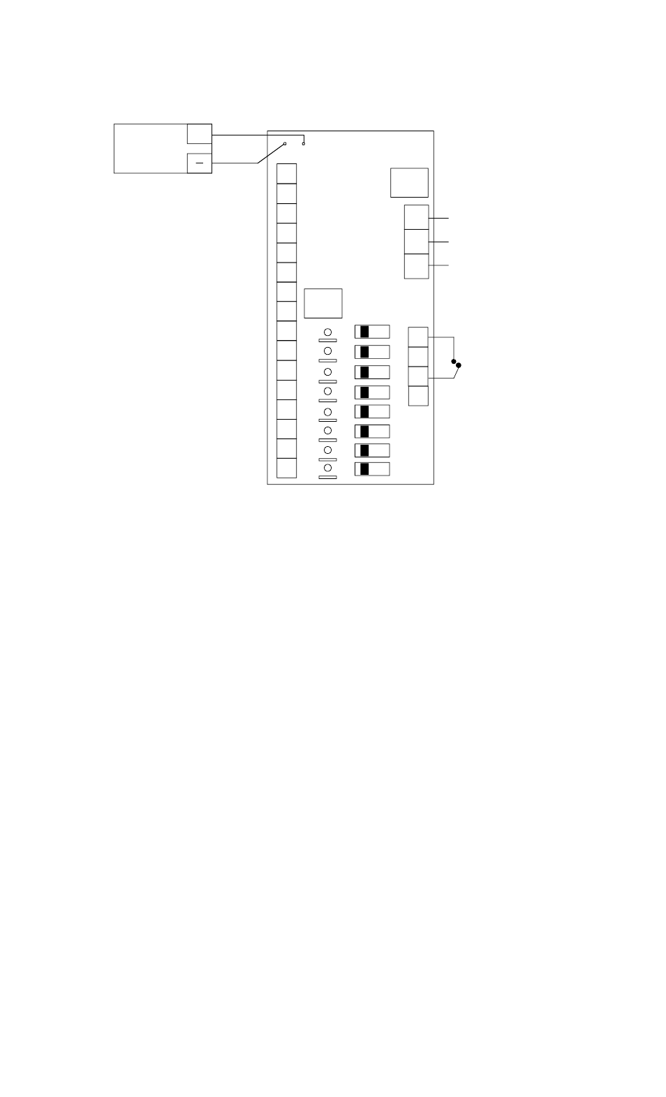
CONNECTIONS FOR POWER SUPPLY USING CCS-8 BOARD
R2
R1
B+
B-
F1
FA
R8
R7
R6
R5
COMMON NEGATIVE
DC RETURN (0 VOLT)
HO
T
N
E
U
T
GR
N
D
1
1
5
VAC
IN
PUT
H
N
G
TERMINALS R1-R8
TERMINALS P1-P8
SUPPLY +V TO EACH iMXD.
EACH TERMINAL IS ON
WHICH IS APPROPRIATE
FOR INSTALLATIONS
WITH MULTIPLE UNITS
FIRE ALARM
N.C. CONTACTS
OPEN WHEN
ALARM ACTIVE
BATTERY
PACK
(OPTIONAL)
+
A SEPARATE POLYSWITCH
F2
AC
FUSE
H
DC
FUSE
R4
R3
RED
BLACK
ON
OF
F
SLIDE SWITCHES POWER AND DE-POWER EACH
"P" OUTPUT. LED'S SHOW OUTPUT STATUS
P2
P1
P8
P7
P6
P5
P4
P3
Note that all Securitron BPS series power supplies have stand-up fuse holders. The 1 Amp units
have an “AC” line voltage fuse only. This fuse will trip if the transformer primary shorts out as it
fuses the incoming 115 VAC. Larger power supplies which employ the CCS-4 or CCS-8 control
boards include an “AC” fuse (see figure 4) which also protects against a transformer primary
short and a “DC” fuse. The DC fuse protects the full DC output of the supply prior to it being
divided through the Polyswitches to the individual “P” outputs. The DC fuse should only trip if
there is a short circuit in the supply itself (downstream short circuits or overloads will trip
individual Polyswitches). This could occur if the F1-H terminal block somehow contacts DC
negative. If the power supply appears dead (all LED’s are out), the problems could be a blown
fuse or the previously described supply shut-down. Always replace any blown fuse with the
same rated fuse.
Terminal FA is a free parking terminal used only with Securitron’s Power Supply Monitor. If you
are using this product, wiring with the FA terminal is shown in the PSM manual. The H terminal
carries +V with the full output of the power supply. It is used for specialty applications where
the full output must be directly connected to a large load. iMXD’s always operate off the “P”
terminals so the “H” terminal is never used.
Interconnection between the fire alarm system and the power supply is a vital part of the exit
delay system function. In a fire, all doors must release immediately. This is accomplished
by mandating a connection with the fire alarm that cuts off all DC power to the doors. This is
the simplest and most sure way to accomplish the function. A UL listed fire alarm system
must be used with latching type dry contacts designed for "auxiliary" operation.
Alarm or trouble contacts may not be used. The contacts must be of sufficient
capacity to switch the total DC current output of the power supply selected. Figure 6
clearly shows the interconnection for the three power supply types offered by Securitron.