Securitron iEXD-24 User Manual
Page 8
PN#
500-18900
Page
8
Rev. D, 10/07
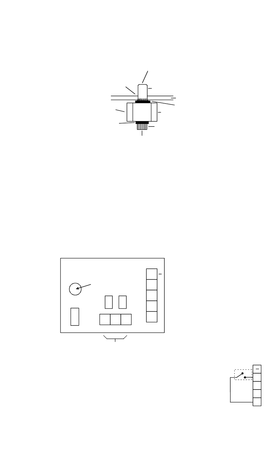
cover mounts utilizing screws into the sub-plate (see the drawing to the right). Do not mount
the cover yet as you will want to check operation of the unit. Mounting the cover is the
final step when everything else is complete.
FIG. 3: COLLAPSING THE BLIND NUTS
4. ADDITIONAL FUNCTIONS
4.1 BYPASS
As has been discussed in the previous sections, the integral keyswitch is employed to relock the
door after a delayed exit event. This occurs when the keyswitch is momentarily turned in the
clockwise direction. If the keyswitch is turned when the door is in the “normal” (secure)
condition, bypass will occur. This releases the door for immediate, authorized exit and keeps it
released for five seconds. After five seconds, the door will resecure. Note that, when automatic
relocking is selected from the Dip Switches, a keyswitch relocking signal will be ignored
(following delayed exit) but bypass can still be performed by turning the key when the system is
secure.
FIG 4: iMXD CONTROL BOARD
4.2 EXTERNAL BYPASS
Any number of external switches can trigger the bypass function
via parallel connections. The switch must be of the normally open
type which will close +V to terminal BP to activate bypass. Note that if
you want to disable use of the integral keyswitch for bypass, just
remove and tie off the wire from the integral keyswitch to terminal BP.
HEADER
TOOL
BLIND NUT
NUT AS SHOWN
PRESS IN BLIND
COLLAPSES WHEN CAP SCREW
IS TURNED WITH ALLEN WRENCH
WHILE TOOL IS HELD FAST
WITH BOX WRENCH
WHILE TURNING WITH ALLEN
WRENCH, PRESS IN TO KEEP
NUT SEATED IN HEADER
HOLD WITH WRENCH OR
CAP SCREW
VISE GRIP WHILE TURNING
TWO FLAT WASHERS
DRILL 3/8" (9.5MM) HOLE
KNURL
CAP SCREW 1/4-20 X 1" (US) OR
6MM-1MM X 25MM (METRIC)
IF SCREW IS STIFF TO TURN,
ADD LUBRICANT TO WASHERS
+
RS
BP
A
EXTERNAL
N.O. SWITCH
TRIGGERS
BYPASS
FUNCTION
C
+
BP
NC
NO
DI
P
S
LOCAL ALARM (+V OUT)
REMOTE ALARM ONE AMP RELAY
RESET INPUT
BYPASS INPUT
0V (NEG) POWER
+V POWER
NOTE: RS and BP INPUTS OPERATE
BY BEING CONNECTED TO +V
NORMALLY ENERGIZED
RS
A
GAP ADJUSTMENT
SCREW