Securitron SABL INSTALLATION User Manual
Page 7
PN#
500-19700
Page
7
Rev. C, 8/07
11.Position the SABL faceplate (keypad) and the lockset lock body/lever assembly
against the face of the door centering the lock body through the 2-1/8” diameter
hole and inserting the faceplate screw standoff (protrusion) into the 3/8” diameter
hole in the door.
12.Ensure that the lock body frame hooks to the latch retainer legs and that the
retractor engages the bolt tail of the latch assembly (Item #8). DO NOT FORCE.
If lock body does not engage latch easily, check door for preparation errors.
13.Using the table below determine which of the four (4) 10-32 UNF (Phillips) pan
head screws (Item #5) provided should be used:
Door Thickness:
Screw Length to use:
1-1/2” or less
1-3/4”
1-9/16 to 1-3/4”
2”
1-13/16 to 2”
2-1/4”
2-1/16” to 2-1/4”
2-1/2”
14.While holding the lock body/faceplate in place, position the battery and electronics
chassis (Item #2) to the inside of the door. Insert the appropriate screw (Item
#5 as determined above) with the lock washer (Item #6) through the hole in
the power chassis. Thread the screw into the threaded standoff of the faceplate
until finger tight – DO NOT completely tighten at this point.
15.Using a screwdriver, install and tighten the upper #6 X 3/4” long screw (Item #4)
through the upper mounting hole of the chassis.
16.Using a screwdriver, firmly tighten the 10-32 UNF (Phillips) pan head screw (Item
#5 - installed in step 14). Ensure that the lock washer (Item #6) is installed
with the 10-32 UNF screw.
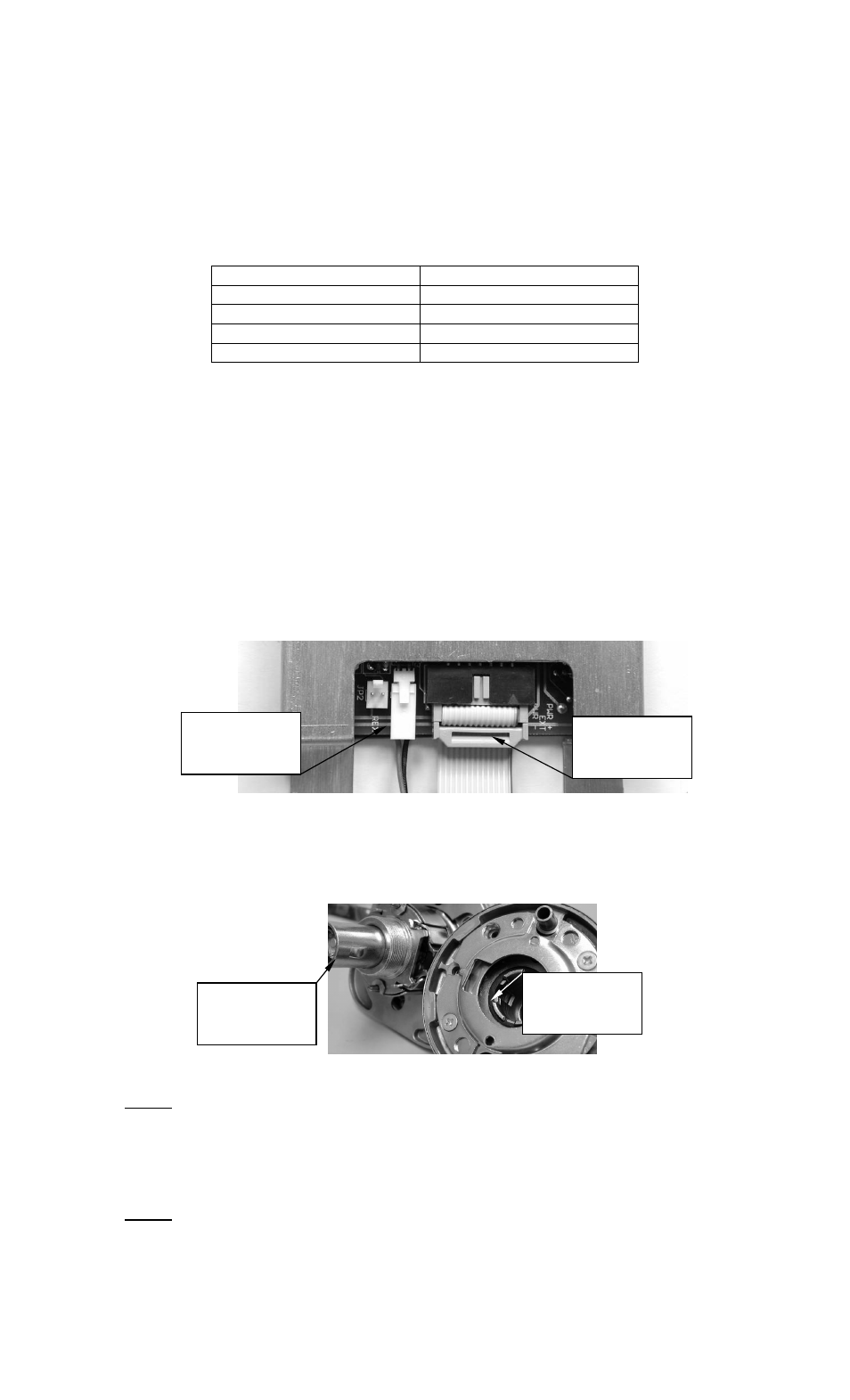
17.Connect the keyed ribbon cable end connector to the keyed terminal on the PC
board of the battery power chassis. Then connect the keyed motor wire connector
to its terminal receptacle on the PC board as shown in Figure 9.
Figure 9
18.Slide the inside rose assembly (Item #13) onto the lock body (Item #14). Note:
The groove inside the rose assembly must line up with the drive lug on the spindle
of the lock body as shown in Figure 10.
Figure 10
Note: Ensure that any excess motor wire is tucked into the 2 1/8” diameter hole in
the door to prevent them from being caught/pinched under the inside rose assembly.
19.Fasten the inside rose assembly in place using the two (2) 10-32 UNF X 2-1/2”
Long (Phillips) flat head screws provided with the lockset (Item #12 – Figure 1).
Note: DO NOT over tighten the lockset screws – as this can compress the assembly
enough to cause binding in the actuation.
Drive Lug of
Lock Body
Spindle
Keyed Groove
inside Rose
Assembly
Motor Wire
Connection
(keyed)
Ribbon Cable
Connection
(keyed)