Securitron SABL INSTALLATION User Manual
Page 5
PN#
500-19700
Page
5
Rev. C, 8/07
SABL Installation:
1. Ensure door has been prepared as described in the previous section.
2. Unpack the SABL from its packaging box.
3. Using a 3/32” hex (Allen) wrench remove the 8-32 UNC X 1/4” long hex socket pan
head screw (Item #7 of Figure 1) and remove the SABL battery access cover
(Item #3) from the battery and electronics chassis (Item #2). Set the screw,
cover and chassis aside for later use.
4. Unpack and disassemble the lockset.
a. Remove the lockset from its packaging box.
b. Using the handle removal tool provided, remove the inside handle of the lockset
(Item #10).
c. Remove the rose scalp (Item #11) from the inside rose of the lockset.
d. Using a screwdriver, remove the two (2) screws (Item #12) holding the inside
and outside rose assemblies together.
Lockset door thickness adjustment:
The lockset as provided is pre-adjusted for a 1-3/4” [44mm] thick door. If adjustment to
accommodate a different door thickness is required, please determine the style of lockset
(“A” or “B”) and refer to the accompanying instructions and illustrations to adjust the
lockset as follows:
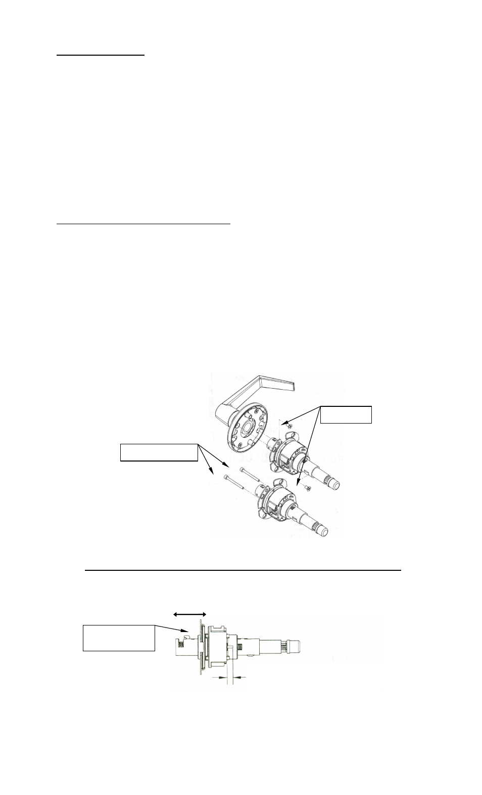
A. Using a screwdriver, remove the two (2) screws holding the lock body to the
outside rose as shown in Figure 5.
B. Remove the lock body from the outside rose assembly.
C. Extract the two (2) alignment pins from out of the lock body as shown in
Figure 5.
D. Adjust the lockset for proper door thickness as described for Style “A” or
“B” – Step E.
Figure 5
Style “A” (lockset with threaded adjustment for door thickness):
E. Rotate outside rose placement plate along the threaded body until the
required distance is achieved as shown in Figure 6.
9/32" (7.1mm) for 1-3/4" (44mm) Door
3/16" (4.7mm) for 2" (51mm) Door
1/16" (1.6mm) for 2-1/4" (57mm) Door
Figure 6
(2) Alignment Pins
(2) Screws
Rose Placement
Plate (Threaded)