Securitron SABL INSTALLATION User Manual
Page 6
PN#
500-19700
Page
6
Rev. C, 8/07
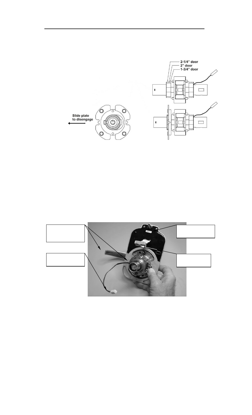
Style “B” (lockset with slotted adjustment for door thickness):
E. Slide outside rose placement plate to one side to disengage it from the lock
body. Position to desired door thickness slot as shown in Figure 7 and
reengage (slide) plate back to center.
Figure 7
F. Insert alignment pins back into position.
G. Fasten lock body to outside rose with two (2) screws removed in step A.
5. Insert the latch assembly (latchbolt) (Item #8) into the hole prepared in the edge
of the door. Insure the beveled edge of the bolt faces toward the strike plate (door
frame) and loosely install using the two (2) mounting screws provided (Item #9).
(DO NOT completely tighten the screws at this point).
6. While holding the SABL faceplate (keypad) (Item #1), insert the end of the outside
rose assembly and lock body (Items #11, 14 and 15 – assembled) along with
the lock motor wire connector through the lockset opening in the faceplate as
shown in Figure 8.
Figure 8
7. Holding this assembly together in one hand, feed the motor wire connector through
the 2-1/8” diameter hole in the door from the front (keypad) side of the door.
8. Retrieve the wire connector from the inside (battery side) of the door and feed the
connector back up and through the 5/16” diameter (diagonal) hole and into the 1”
diameter hole above (see hole configuration – Figure 4).
9. Again, from the inside (battery side) of the door, retrieve the motor wire connector
currently in the 1” diameter hole and using needle-nose pliers carefully pull it out
through the hole to the battery side of the door.
10.Feed the keypad ribbon connector from the keypad side of the door through the 1”
diameter hole and out the battery side of the door.
Lock Motor Wire
& Connector
Outside Rose,
Lock Body and
Lever Handle
SABL Faceplate
(Keypad)
Ribbon Cable
& Connector