Document configuration settings – Securitron M380BD_C_C2_X MAGNALOCK_Series User Manual
Page 8
PN# 500-23310
Page 8
Rev. B 06/14
J8
Terminal Block 8
BondSTAT
A 2-wire terminal block providing a contact in which
(NO/NC) state change is determined by Jumper 3 when
the BondSTAT (magnetic bond) is interrupted.
J12
Terminal Block 12
Door Position Switch
A 2-wire terminal block providing a contact in which
(NO/NC) state change is determined by Jumper 4 based
on the magnet’s contact with the strike plate.
J6
Terminal Block 6
Alternate Input
A 2-wire terminal block providing a dry contact connection
for external control input.
J7
Terminal Block 7
Alternate (REX)
Output
A 2-wire terminal block providing a connection for an
alternate output.
Video
Connection
(Camera
Interface PCB)
Terminal Block
Connection for
Camera Signal
The included Balun and BNC cable adapter can be used to
rout wiring through either side of the Magnalock housing
for connection to surveillance system.
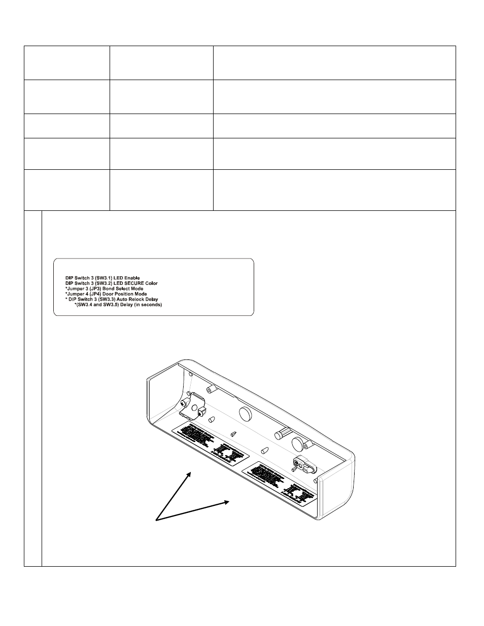
3.
Document Configuration Settings
The configuration settings are now complete. Copy your settings onto the adhesive-backed Circuit Board
Settings label enclosed with the mounting hardware packet.
Important! Complete the label and affix to the inside cover of your Magnalock
®
This information will be needed if the lock needs to be serviced, replaced or inspected.
M370/M380 Settings
www.securitron.com
1-800-624.5625
ON=ENABLED
ON=RED
1-2=NC
1-2=NC
ON=ENABLED
OFF=DISABLED
OFF=GREEN
2-3=NO
2-3=NO
OFF=DISABLED
5 10 20 30
* available on M380BD models only
Note: The example shows the Default
settings. Your settings may vary, based on
your checklist.
NO = Normally Open
NC = Normally Closed