Securitron M380BD_C_C2_X MAGNALOCK_Series User Manual
Page 6
PN# 500-23310
Page 6
Rev. B 06/14
Component Label
Component Name
Selection
Position
SW3
DIP Switch SW3.1:
LED Enable
Position 1 setting of the
DIP switch enables or
disables the display of
the LED for lock status.
ON = LED ENABLED
(default setting)
Position 1 ON (default)
OFF = LED DISABLED
Position 1 OFF
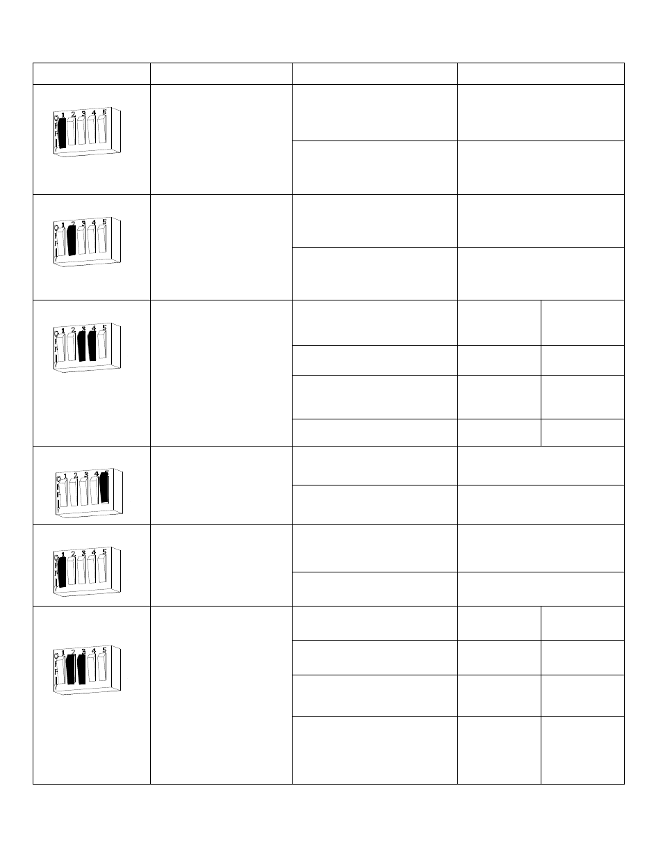
SW3
DIP Switch SW3.2:
LED Color Select
Position 2 setting of the
DIP switch controls the
color of the LED
output. Output options
are red or green.
ON = SECURE = RED
Position 2 ON
OFF = SECURE = GREEN
(default setting)
Position 2 OFF (default)
SW3
DIP Switch SW3.3,
SW3.4:
Relock Delay Timer:
The Auto Relock Delay
can be adjusted by
selecting a time delay
with position 3 and
position 4 of SW3.
1/2 second delay
(default)
Position 3
OFF
Position 4
OFF
3 second delay
Position 3
OFF
Position 4
ON
7 second delay
Position 3
ON
Position 4
OFF
15 second delay
Position 3
ON
Position 4
ON
SW3
DIP Switch SW3.5:
PIR Model Position 5
is set by the factory.
This switch should not
be changed
PIR Model
Position 5 ON
Non-PIR Model
Position 5 OFF
SW1
DIP Switch SW1.1:
PIR Sensitivity
Position 1 setting of the
DIP switch sets the PIR
Sensitivity.
Medium Sensitivity
(default setting)
Position 1 OFF (default)
High Sensitivity
Position 1 ON
SW1
DIP Switch SW1.2,
1.3:
PIR Cone
Adjustment
Position 2 and 3 of
SW1 adjust the PIR
sensing cone.
See page 18
Wide Beam (default)
Position 2
OFF
Position 3
OFF
Narrow Beam
Position 2 ON
Position 3
ON
Narrow Plus Left
Position 2
ON
Position 3
OFF
Narrow Plus Right
Position 2
OFF
Position 3
ON