Securitron M380BD_C_C2_X MAGNALOCK_Series User Manual
Page 18
PN# 500-23310
Page 18
Rev. B 06/14
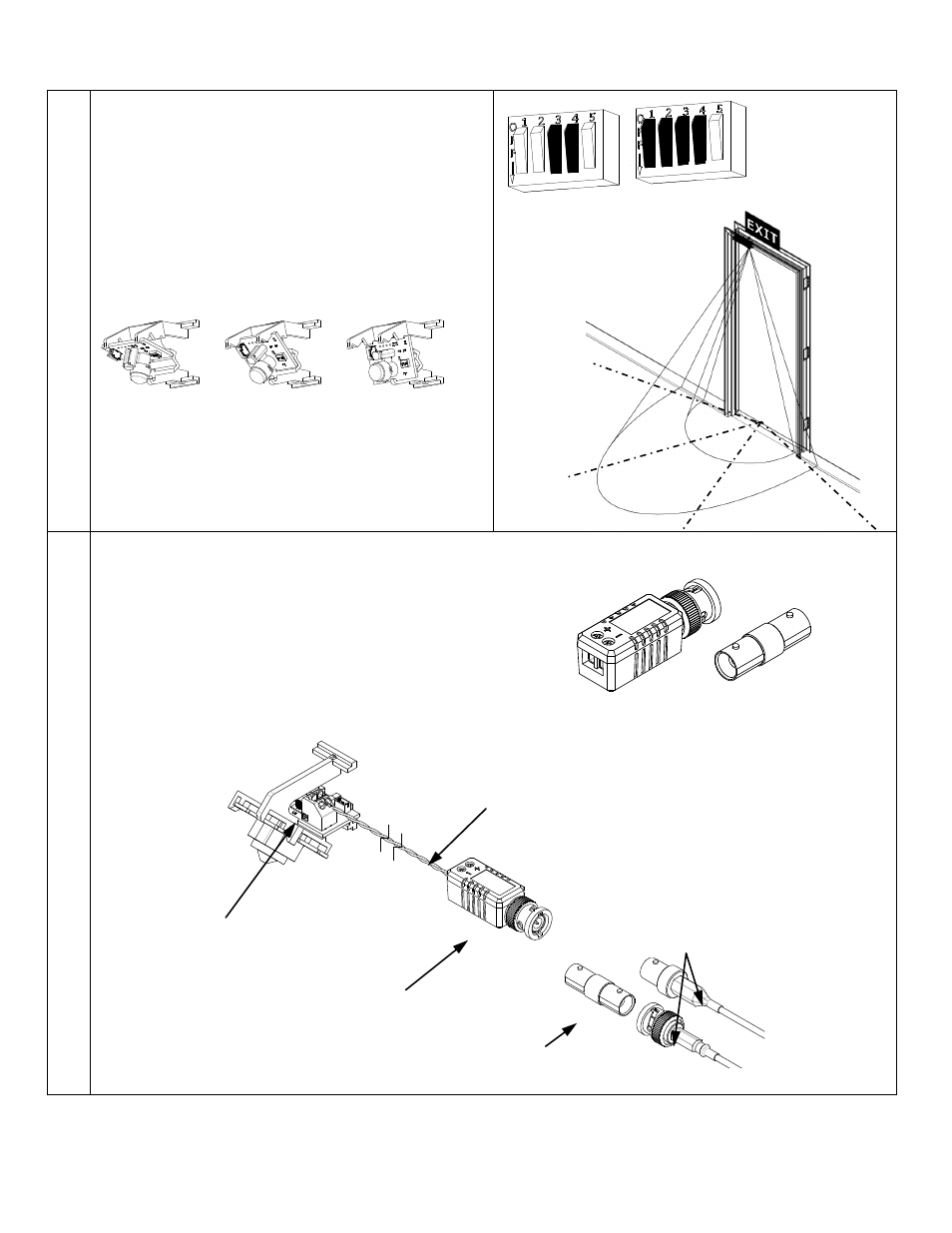
3.
Motion Detector Models:
Models equipped with a motion detector have
control features accessed by the DIP Switches
SW3 and SW1 settings (see pages 6 and 7).
The relock delay timer is set with SW3.3 and 4.
Sensitivity and zone width are set with SW3
Position 1,2 and 3.
The PIR ambient light compensation feature is
enabled/disabled using SW3 Position 4.
Note: For increased range the motion detector sensor
PC board may be repositioned in the modular bracket.
4.
Camera Models:
The camera module features an interface PC
board which includes a 2-position terminal block.
Connect the camera to your security system
with a 2-wire, (twisted pair) from the 2-position
interface board terminal block to the included
video transceiver balun.
A BNC straight adapter is also included for
connections to a male BNC connector.
Transceiver Balun
Camera Interface
Connection Terminal
Twisted Pair
Wire Connection
(Not Included)
Male OR Female
BNC Connector from
CCTV Equipment
(Not Included)
BNC Straight
Adapter
SW3
SW1
Narrow
Right
Left