Rivers Edge RE607 22' Timbershot User Manual
Page 8
Check for parts online at
www.huntriversedge.com or call 800-450-EDGE (3343) M-F 8-5
Check for parts online at
www.huntriversedge.com or call 800-450-EDGE (3343) M-F 8-5
8
Operator's Manual
Rivers Edge® One-Man Ladder Stands
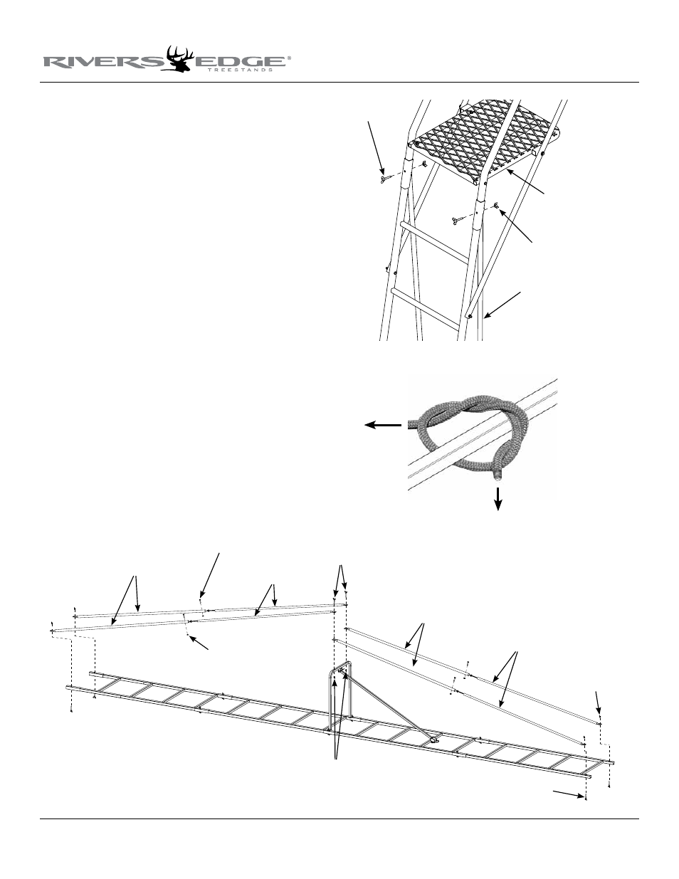
Figure 5
truss male braces
truss female braces
truss male braces
locknuts
1/4-20 x 1-1/4" bolts
this end of ladder
assembles to
top platform section.
wing nuts
truss female braces
1-3/4" wing bolts
wing nuts
wing bolts
Figure 7
Figure 6
1-3/4" wing
bolts
wing nuts
assembled top
platform section
assembled truss
braces
c. Attach the opposite end of lower brace assemblies to the bottom
ladder section using (2) provided 1/4-20 x 1-3/4” wing bolts and
wing nuts. sEE fIGuRE 5.
notE: lifting on the bottom end of ladder will be needed to help
align the holes in the flattened end of brace assemblies to the slots
in the bottom ladder section as you are completing the pre-built
strength “arch” in the ladder assembly. this is normal.
d. Secure the first and second ladder sections as well as the third
and fourth ladder sections together using (4) provided 1/4-20 x
1-3/4” wing bolts and wing nuts. sEE fIGuRE 6.
12. Tighten all wing bolt/wing nut combinations securely by hand.
Be sure not to over tighten or crush tubing. Double and triple
check all hardware locations to make sure they are all securely
fastened.
13. Tie one end of each of the provided 22’ ropes to the platform side
rails, just in front of the tree blade. Be sure your double knots are
secure. sEE fIGuRE 7.
b. Attach the remaining (2) assembled braces and the opposite end
of previously assembled braces to the truss support using (2)
provided 1/4-20 x 1-3/4” wing bolts and wing nuts. You must attach
the flattened end of braces so that it will cause the lower braces to
angle towards the bottom end of ladder. It is recommended to
position the female end of these lower brace assemblies to the truss
support so water will drain freely during use. sEE fIGuRE 5.
notE: lifting on the bottom end of ladder will be needed to help
align the holes in the flattened end of brace assemblies to the holes
in the truss support as you are beginning to put the pre-built
strength “arch” in the ladder assembly. this is normal.