Rivers Edge RE607 22' Timbershot User Manual
Page 29
Check for parts online at
www.huntriversedge.com or call 800-450-EDGE (3343) M-F 8-5
29
Operator's Manual
Rivers Edge® One-Man Ladder Stands
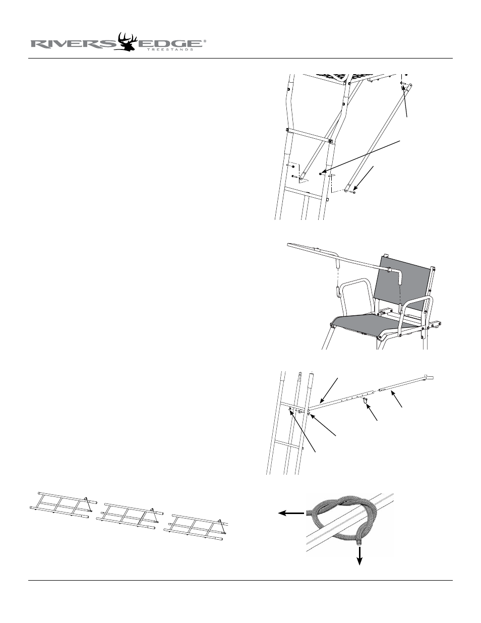
16. Sections are assembled on the ground in the following order;
bottom section (10166 3-step ladder); second section (10168 3-step
ladder with stabilizer bar hole); third section (10168 3-step ladder
with stabilizer bar hole); fourth section (10170 3-step ladder w/
support brace mounting holes); top section (assembled top platform
section). sEE fINIshED uPPERCuT lADDER.
17. With all sections assembled together on ground, secure all sections
together using (3) provided spring lock pins. sEE fIGuRE 11.
18. Attach the (2) support braces (410024) to the inside of lower tree
blade and outside of top ladder section w/ mounting holes using
(4) provided 1/4-20 x 1-1/2” bolts and locknuts. sEE fIGuRE 12.
Tighten securely. Be sure not to over tighten or crush tubing
when tightening!
19. a. Attach the removable shooting rail by setting rail down over studs
provided on armrests sEE fIGuRE 13. Lubrication is recommended
to prevent binding and noise.
b. Attach the (2) provided 9” and (1) provided 47” camo foam pads
to the armrests and shooting rail by wrapping around tubing and
attaching Velcro® together.
c. Attach foam padded seat bumpers (48102) to bottom side of
front seat spacer weldment. Surface must be clean and at room
temperature to assure proper adhesion.
20. a. Attach the stabilizer bar extension tube (48053) to the second
ladder section mounting hole using (1) provided 1/4-20 x 2-1/4”
wing bolt and wing nut. sEE fIGuRE 14.
b. Slide the stabilizer bar (48052) into the extension tube and attach
the two pieces together using (1) provided spring lock pin. Spring
lock pin must go through both the extension tube and stabilizer
bar at appropriate hole to achieve desired distance from tree.
Adjustment in length may be needed when ladder is uprighted later
in instructions. sEE fIGuRE 14.
21. Tie one end of each of the provided 20’ ropes to the square tube of
tree blade frame, just in front of the tree blades. Be sure your double
knots are secure. sEE fIGuRE 15.
Figure 12
1/4-20 x 1-1/2" bolts
locknuts
1/4-20 x 1-1/2" bolts
Figure 13
Figure 14
extension tube
1/4-20x 2-1/4 wing bolt
1/4-20 wing nut
stabilzier bar
snap lock pin
Figure 11
Figure 15