Rivers Edge RE607 22' Timbershot User Manual
Page 21
Check for parts online at
www.huntriversedge.com or call 800-450-EDGE (3343) M-F 8-5
21
Operator's Manual
Rivers Edge® One-Man Ladder Stands
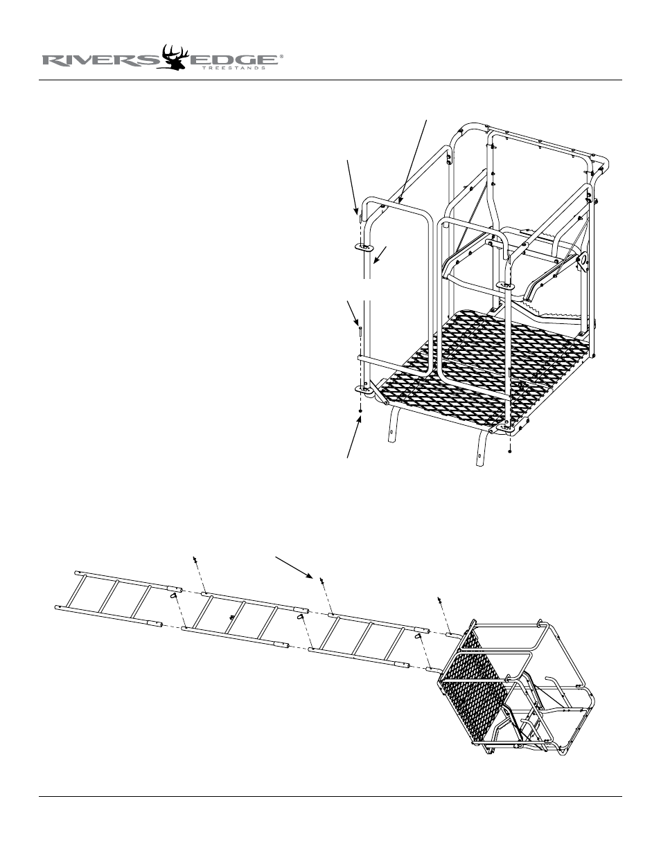
17. Attach (2) door weldments (410017) to the door mount weld-
ments by inserting welded rod and square tube of door frame into
the locking position on the upper door mount frame plates. Attach
the lower portion of each door to the lower door mount plate us-
ing (2) provided 1/4-20 x 1-3/4” bolts and locknuts. sEE fIGuRE
11. Tighten nut only so that the bolt protrudes through nyloc
nut so that it is flush.
Test by lifting each door out of the lock position and making sure
the pivoting rod at the top of each door does not come out of the
upper door mount plates. Test the locking feature of each
door by dropping each door into the upper door mount plates al-
lowing the square tube portion of each door to securely lock.
notE: Make sure both doors are functioning properly at all
times. doors should pivot freely to and from the lock position.
nuts should be adjusted on bottom of doors to allow free travel,
but not allow the door pin at top to pull out of upper door mount
plates.
18. You must now tighten all remaining nut & bolt assemblies. Be
sure not to over tighten or crush tubing when tightening!
19. Sections are assembled on the ground in the following order; bot-
tom section (410025 3-step ladder); second section (410027 3-step
ladder with stabilizer bar mount); third section (410028 3-step lad-
der w/ mounting holes); top section (assembled top platform sec-
tion). sEE fINIshED 15’ OPENING DAY lADDER.
20. With all sections assembled together on ground, secure all sec-
tions together using (6) provided spring lock pins. Handle of
spring lock pin must be put to the outside of ladder side rails.
sEE fIGuRE 12.
Figure 12
Figure 11
1/4-20 x 1-3/4”
bolts
locknuts
spring lock pins
door mount
weldment
welded rod and
square tube
door weldments