Rivers Edge RE607 22' Timbershot User Manual
Page 7
Check for parts online at
www.huntriversedge.com or call 800-450-EDGE (3343) M-F 8-5
7
Operator's Manual
Rivers Edge® One-Man Ladder Stands
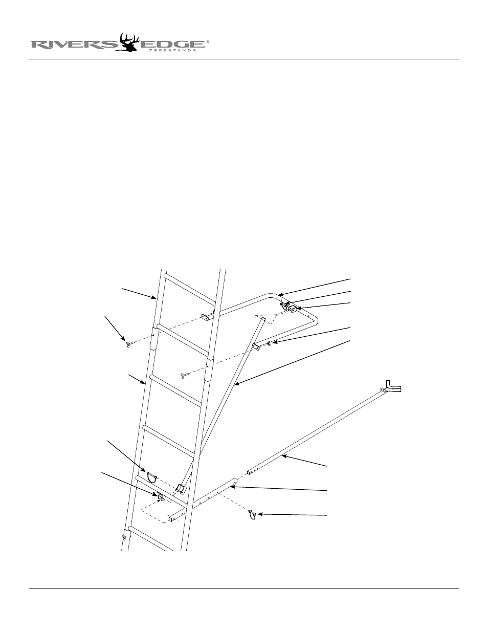
8. Attach the truss support (48023) to where the second and third
ladder sections have been slid together, using (2) provided 1/4-20
x 1-3/4” wing bolts and wing nuts. sEE fIGuRE 4.
9. a. Attach the counter lock support bar (48025) to the truss support
mounting bracket using (1) provided 1-3/4” spring lock pin. sEE
fIGuRE 4.
b. Attach the opposite end of counter lock support bar and the
stabilizer bar extension tube (1ML23) to the second ladder section
mounting bracket using (1) provided 2-1/2” spring lock pin. sEE
fIGuRE 4.
notE: pin may have a tight fit. this is normal due to the counter
lock support bar acting as a locking bar. You may need to
temporarily loosen the wing nuts/bolts on truss support to help
with hole alignment. Retighten wing nuts/bolts when complete.
c. Slide the stabilizer bar (L17) into the extension tube and attach the
two pieces together using (1) provided 1-3/4” spring lock pin. Spring
lock pin must go through both the extension tube and the stabilizer
bar at appropriate hole to achieve desired distance from tree.
Adjustment in length may be needed when ladder is uprighted later
in instructions. sEE fIGuRE 4.
Figure 4
stabilizer bar
extension tube
spring lock pin
third ladder section
1-3/4" wing bolts
second ladder section
2-1/2" spring lock pin
second ladder
section mounting
bracket
truss support
spring lock pin
truss support mounting bracket
wing nut
counter lock support bar
10. Insert the (4) truss male braces (48041) into the (4) truss female
braces (48040). Have the flattened end of the braces oriented in
opposite directions of each other and align the holes to secure the
braces together using (4) provided 1/4-20 x 1-1/4” bolts and locknuts.
sEE fIGuRE 5 ON fOllOWING PAGE. Tighten securely, being
careful not to over tighten or crush tubing!
notE: You must be sure to have the flattened ends of braces ori-
ented in opposite directions of each other so they will align prop-
erly (flush) to the mating parts later on in assembly.
11. a. Attach (2) assembled braces to where the fourth ladder section and
assembled top platform section have been slid together using (2)
provided 1/4-20 x 1-3/4” wing bolts and wing nuts. You must attach
the flattened end of these braces so that it will cause them to angle
away from the ladder, towards the rounded end of truss support. It is
recommended to position the female end of these upper brace
assemblies to the top of the ladder so water will drain freely during
use. sEE fIGuRE 5 AND 6 ON fOllOWING PAGE.