FEC AFC1500 User Manual
Page 61
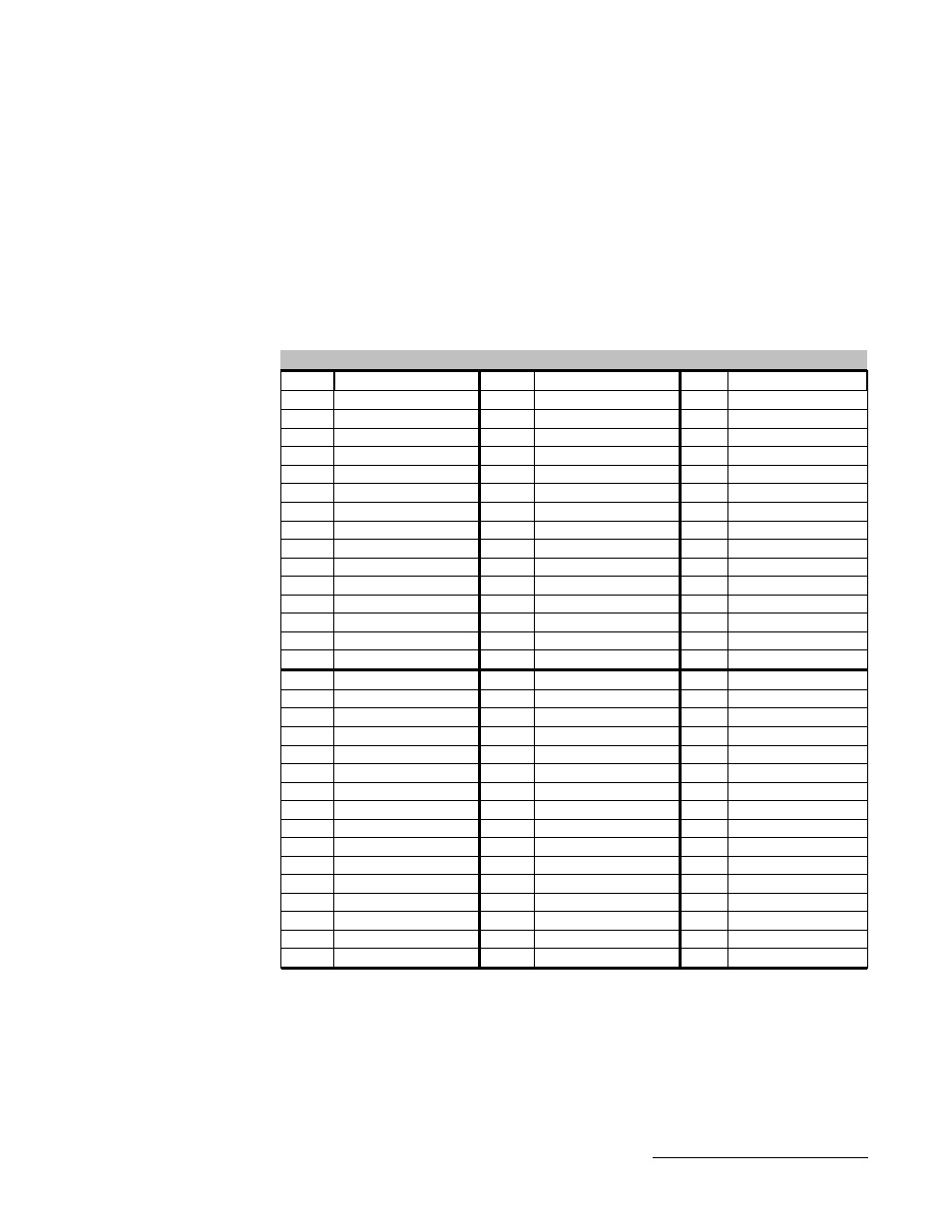
Typical I/O Layout (Fieldbus)
The following I/O layout map is provided as a typical reference of the bit
addressing for FIELDBUS systems. This is only a reference and NOT
intended for any particular application or fieldbus type. See your application’s
Electrical Control Schematic drawings for your actual I/O layout.
Note: The inputs are permanently set in the location shown and cannot be
changed. However, the Output locations are programmable and may not
reside in the locations shown.
Inputs
Not Used
96*
Not Used
64
Data Sel. 2 (N/A)
32
Not Used
95
Not Used
63
Data Sel. 1 (N/A)
31
Not Used
94
Not Used
62
Data Sel. 0 (N/A)
30
Not Used
93
Not Used
61
Not Used
29
Not Used
92
Not Used
60
Not Used
28
Not Used
91
Not Used
59
Not Used
27
Not Used
90
Not Used
58
Spindle Bypass 10
26
Not Used
89
Not Used
57
Spindle Bypass 9
25
Not Used
88
Not Used
56
Spindle Bypass 8
24
Not Used
87
Not Used
55
Spindle Bypass 7
23
Not Used
86
Not Used
54
Spindle Bypass 6
22
Not Used
85
Spindle Bypass 31
53
Spindle Bypass 5
21
Not Used
84
Spindle Bypass 30
52
Spindle Bypass 4
20
Not Used
83
Spindle Bypass 29
51
Spindle Bypass 3
19
Not Used
82
Spindle Bypass 28
50
Spindle Bypass 2
18
Not Used
81
Spindle Bypass 27
49
Spindle Bypass 1
17
Not Used
80
Spindle Bypass 26
48
Input Port 3
16
Not Used
79
Spindle Bypass 25
47
Input Port 2
15
Not Used
78
Spindle Bypass 24
46
Input Port 1
14
Not Used
77
Spindle Bypass 23
45
Input Port 0
13
Not Used
76
Spindle Bypass 22
44
Not Used
12
Not Used
75
Spindle Bypass 21
43
Not Used
11
Not Used
74
Spindle Bypass 20
42
Cyc. Count Reset
10
Not Used
73
Spindle Bypass 19
41
Cycle Count - Up
9
Not Used
72
Spindle Bypass 18
40
Seq. Select 3
8
Not Used
71
Spindle Bypass 17
39
Seq. Select 2
7
Not Used
70
Spindle Bypass 16
38
Seq. Select 1
6
Not Used
69
Spindle Bypass 15
37
Seq. Select 0
5
Not Used
68
Spindle Bypass 14
36
Start
4
Not Used
67
Spindle Bypass 13
35
Reverse
3
Not Used
66
Spindle Bypass 12
34
Reset
2
Not Used
65
Spindle Bypass 11
33
Stop
1
Input
Bit
Input
Bit
Input
Bit
*Note: The number of data bits reserved for inputs varies with the type of
fieldbus interface. It varies between 16 & 256 (or more), even though the
number of inputs are limited to this list. See your applications Electrical
Drawings for this information.
Chapter 4: I/O and Output Data
61