FEC AFC1500 User Manual
Page 46
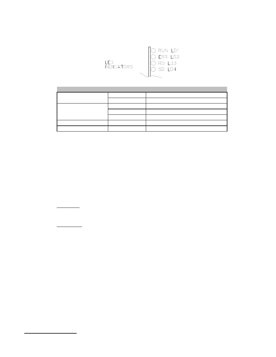
Indication LED
Module Reading Data
Read Data
RD
Module Sending Data
Send Data
SD
Communication error at Station
ON - Flashing
Communication error at all Stations
ON - Steady
Normal
OFF
ERR
Module is Normal - Running
ON
Watchdog Timer error
OFF
RUN
Status LEDs
Configuration
Configuration of the CCLink system is done in the PLC Logic. It is essential
that this configuration matches the Dip Switch settings of the FEC CCLink
slave. FEC is considered a “Remote Device” in the PLC configuration. The
number of “Occupied Stations” set in the PLC must also match the Dip Switch
set-up. (Note: The last 16 output addresses are used by the CCLink
communication & cannot be used by the user) Below is an example of the
PLC configuration setting for the FEC Node in the CCLink network;
Command
[MOV H1306 D19]
Description
MOV = Move command
H = Hex number being used
1 = Remote Device (0= Remote I/O Station, 2= Intelligent Device)
3 = 3 Occupied Stations (3 x 32I/O = 96 Inputs & Outputs, (4 is max.))
06 = Station #6 (CCLink address, 64 max.)
D19 = PLC register which stores the configuration (could be any register #)
Note: This is only an example of the station setting configuration. Other
configuration must be completed in the PLC logic for proper operation. The
PLC configuration MUST match the settings of the FEC Dip Switches. The
communication link will not be established and the red “ERR” LED will be lit
if these settings do not match. Please review the Mitsubishi CCLink manual
#13J872 for further information.
Chapter 3: Control Interfaces
46