FEC AFC1500 User Manual
Page 55
Bypass’s spindle #31 - Spindle is ignored as if it does
not exist.
Bypass Spindle
#31
55*
.
.
.
Bypass’s spindle #11 - Spindle is ignored as if it does
not exist.
Bypass Spindle
#11
35*
Bypass’s spindle #10 - Spindle is ignored as if it does
not exist.
Bypass Spindle
#10
26*
.
.
.
Bypass’s spindle #1 - Spindle is ignored as if it does not
exist.
Bypass Spindle
#1
17*
Data Select 2
32
Data Select 1
31
These lines form a binary code to select up to 8 Output
Data Banks. Used for Digital I/O interfaces. NOTE: Not
Used for Fieldbus interfaces.
Data Select 0
30
Multi Unit Input Signals
* Spindle Bypass signals can only be used with a Fieldbus interface (except
spindle 1-10 is available in discrete I/O) . If using the Discrete I/O interface
the spindle bypass signals are wired from the SAN Unit PLC connector (if you
have more than 10 spindles) . See I/O layout for input location in fieldbus.
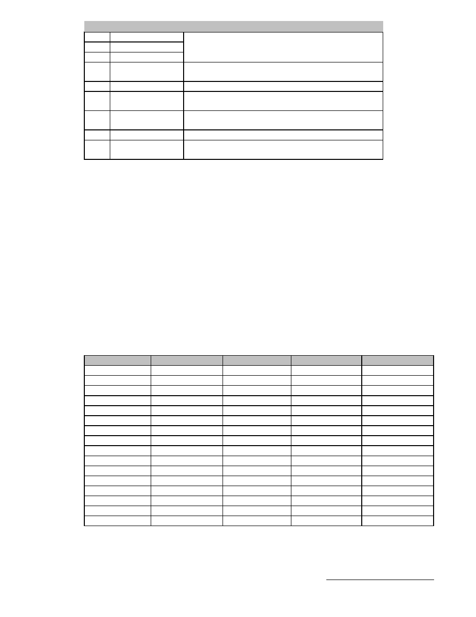
Sequence Select Table
Sequences are selected using the Sequence Select Bits 0-3. Using these four
bits in a binary fashion, 16 sequences can be selected. With all bits “OFF”,
sequence #1 is selected and with all bits “ON”, sequence #16 is selected. The
Sequence must be set before the start signal is received. It is recommended
when using multiple sequences that the Sequence Output signals (SEQ. 0-3)
be used to confirm which sequence is selected BEFORE starting the cycle.
on
on
on
on
16
on
on
on
off
15
on
on
off
on
14
on
on
off
off
13
on
off
on
on
12
on
off
on
off
11
on
off
off
on
10
on
off
off
off
9
off
on
on
on
8
off
on
on
off
7
off
on
off
on
6
off
on
off
off
5
off
off
on
on
4
off
off
on
off
3
off
off
off
on
2
off
off
off
off
1
Seq Select 3
Seq Select 2
Seq Select 1
Seq Select 0
Sequence
Chapter 4: I/O and Output Data
55