FEC AFC1500 User Manual
Page 44
Termination
Termination of the CCLink requires a terminating resistor at each end of the
fieldbus. Connect 120 ohm resistor between the DA & DB terminals if this is
the last connection. (Remember that the CCLink master also needs to be
terminated)
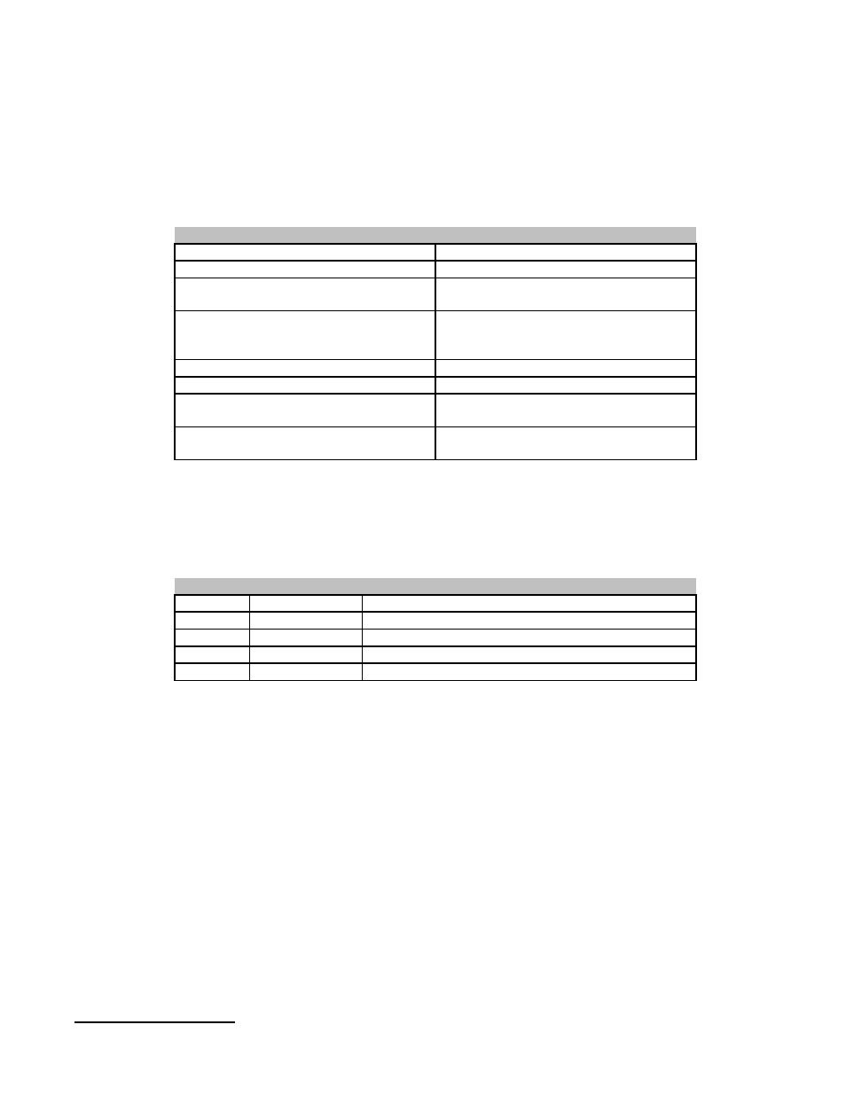
I/O addressing set by PLC TO / FROM
commands in Logic
I/O Configuration*
128 inputs, 128 outputs max. Size set
in groups of 32 I/O (Occupied Stations)
Maximum Cyclic I/O Size
HDLC Standard
Transmission Format
Master/Slave - EIA RS485
Communications Type
Shielded Copper Twisted Pair
Mitsubishi BA1SJ61-(m) m=Meters
Belden 8102 or equivilent
Cable
1200m max. at 156K baud / 50m max.
at 10Mbit/s
Distance
64 Max.
Stations
156K - 10M baud - selectable
Speed
CC Link Specifications
* Actual I/O addressing must be assigned in the PLC logic. See the
Mitsubishi User Manual # 13J872 Control & Communication - Link System
Master / Local Module for logic reference. (Ref. Section 10)
Field Ground
FG
Pin 5
Connect cable shield
SHIELD
Pin 4
Digital Ground
DG
Pin 3
Communication Line
DB
Pin 2
Communication Line
DA
Pin 1
CC-Link connector
Connector: 5.08mm BU04/5 Hartmann or Equivalent
Wiring of the CC-Link network should be performed by using the cable listed
above in the CC-Link Specifications. The three twisted conductors should be
wired in series to each CC-Link device, using a terminating resistor at the
Master end and on the last Remote/Local device between the DA & DB
terminals. Connection should be DA to DA, DB to DB, DG to DG with the
cable shield connected to the SHIELD terminal. The field ground (FG) should
be connected to earth ground.
Chapter 3: Control Interfaces
44