FEC AFC1500 User Manual
Page 37
Termination
Termination of the fieldbus requires a terminating resistor at each end of the
fieldbus. These resistors should have a value of 121 ohms.
EDS File
Each device on a DeviceNet network is associated with an EDS file containing
all necessary information about the device to be connected. The network
configuration program uses this file during configuration of the network.
The EDS file associated with the FEC device can be downloaded from the
FEC website. www.fec-usa.com (file: abs.eds)
Direct link:www.fec-usa.com/fecusacomnew/support/index.htm
(the file can also be downloaded directly from HMS - www.hms.se)
Note: The FEC system will appear in the network Vendor list as “HMS
Fieldbus Systems” and in the network as “Anybus-S Devicenet” adapter. This
is the manufacturer of the interface board which is integrated into the Multi
Unit.
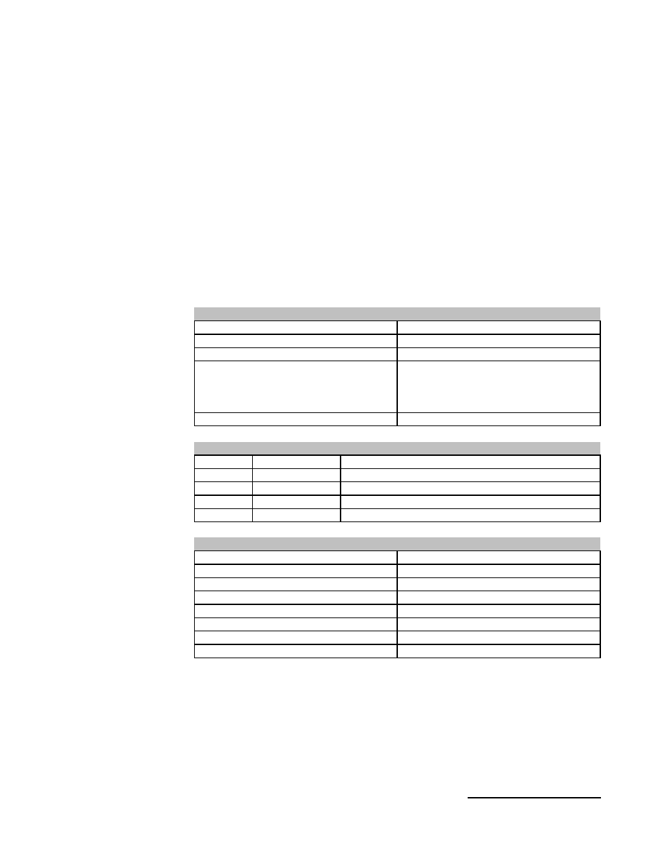
Master/Slave
Communications Type
Twisted
pair for signal and power
Allen Bradley or equivalent ;
Thin Cable #1485C-P1-C
Thick Cable # 1485C-P1-A
Cable
500m max.
Distance
64
Nodes
500K baud max.
Speed
DeviceNet Specifications
Red
V+
Pin 5
White
CAN_H
Pin 4
Drain/Shield
Pin 3
Blue
CAN_L
Pin 2
Black
V-
Pin 1
DeviceNet connector
Dual Port RAM or Serial Interface
Interface type
2 Maximum
Servers per group
4 LEDs for module and network status
Status indicator
512 max.*
Input data bytes
512 max.*
Output data bytes
Board switches 3 to 8
MAC ID setting
Board switches 1 & 2
Baud rate configuration
+5V, 200 ma
Operating Voltage
Interface Board Specifications
* Typical configuration is 32 Bytes (256 I/O points) but can be altered using
the AFC Software package. (See AnyBus-S Reference at the end of this
chapter for I/O Setting example.)
See section 4 (I/O signals) for reference of typical fieldbus I/O layout.
Operation Note: The first 16 bits of I/O are used by Devicenet
communication. The first input must be set “ON” to enable communication.
Chapter 3:
Control Interfaces
37