FEC AFC1500 User Manual
Page 45
64
OFF
ON
ON
OFF
OFF
ON
OFF
OFF
.
.
.
.
.
.
.
.
.
47
OFF
ON
OFF
OFF
OFF
ON
ON
ON
.
.
.
.
.
.
.
.
.
10
OFF
OFF
OFF
ON
OFF
OFF
OFF
OFF
.
.
.
.
.
.
.
.
.
2
OFF
OFF
OFF
OFF
OFF
OFF
ON
OFF
1
OFF
OFF
OFF
OFF
OFF
OFF
OFF
ON
Station
#
SW-8
SW-7
SW-6
SW-5
SW-4
SW-3
SW-2
SW-1
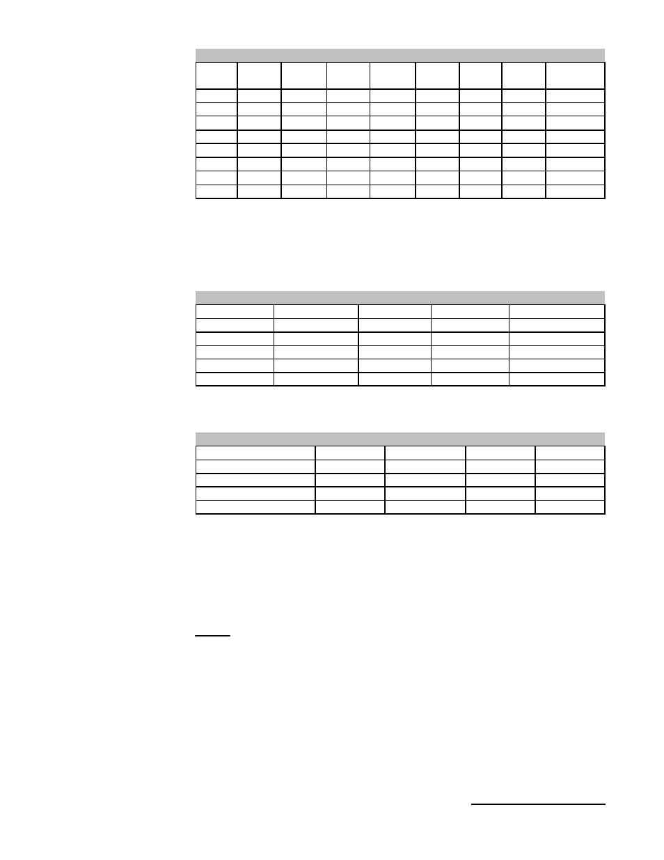
Station Number Setting (SW1)
Station Number sets the address in the CC-Link network. Max. number of
stations is 64. No two devices may share the same address. Switch setting
format is Binary Coded Decimal (BCD) Switch 1-4 is Least Significant Byte
(LSB). Switch 5-8 is Most Significant Byte (MSB). This switch must be set
before power is on, and cannot be changed during operation.
10M
OFF
ON
OFF
OFF
5M
OFF
OFF
ON
ON
2.5M
OFF
OFF
ON
OFF
625K
OFF
OFF
OFF
ON
156K
OFF
OFF
OFF
OFF
Baud rate
SW-4
SW-3
SW-2
SW-1
Baud rate setting (SW2)
This setting MUST match the setting of the Master module. This switch must
be set before power is on, and cannot be changed during operation.
OFF
ON
OFF
OFF
4 (128 In/128 Out)
OFF
ON
ON
OFF
3 (96 In/96 Out)
OFF
ON
OFF
ON
2 (64 In/64 Out)
OFF
ON
ON
ON
1 (32 In/32 Out)
SW-4
SW-3
SW-2
SW-1
Number of Stations
Number of Occupied Stations (SW3)
Occupied Stations setting determines the number of 32 bit station buffer
memory locations that will be allocated for this station in the Master buffer
memory. This sets the number of total I/O available for the station. Each
memory bit has a designated input AND output buffer. So a setting of (1) 32
station actually allocates 32 input & 32 output locations for a total of 64 total
points. This switch must be set before power is on, and cannot be changed
during operation.
NOTE: See FEC Electrical Controls drawings for actual setting required as
this may vary per application.
Chapter 3:
Control Interfaces
45