Teledyne GC-Pro/TCD - Gas Chromatograph User Manual
Page 42
Installation GC-ProTCD
Teledyne
Analytical
Instruments
28
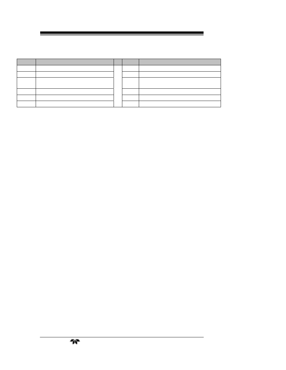
pin #
Description
pin #
Description
20 Alarm 3 C Contact
45
Alarm 1 NC Contact
21 IDLE Contact 1 (one shot only)
46
Alarm 1 NO Contact
22
MEASUREMENT Contact 1 (one
shot only)
47
23 - Output 0-1 v (Channel 2)
48
Exhaust Solenoid Return
24 + Output 0-1 v (Channel 1)
49
25
50
Sample Solenoid Return
3.3.2.10
RS-232
P
ORT
The digital signal output is a standard RS-232 serial communications
port used to connect the analyzer to a computer, terminal, or other digital
device. It requires a standard 9-pin D connector.
Input: The input functions using RS-232 that have been implemented
to date are described in Table 3-7.
Table 3-9: Commands via RS-232 Input
Command Description
AS
Auto Span immediately (continuous mode)
SV
Switch to Span Valve
ZV
Switch to Zero Valve
AV
Switch to Analyze Valve
C1
If in 1Shot mode, start a cycle
C2
If in 1Shot mode, start a span cycle
PMA
Switch to standard message
PMB
Switch to TCD output mode
PMC
Switch to Query Mode (used for interface with
OPC server)
Implementation: The RS-232 protocol allows some flexibility in its
implementation. Table 3-8 lists certain RS-232 values that are required
by the Standard Mode GC-Pro TCD implementation.
Table 3-10: Required RS-232 Options
Parameter Setting
Baud
9600
Byte
8
bits