Teledyne GC-Pro/TCD - Gas Chromatograph User Manual
Page 34
Installation GC-ProTCD
Teledyne
Analytical
Instruments
20
3.3.2.2
F
USE
I
NSTALLATION
The fuse block, at the right of the power cord receptacle, accepts US
or European size fuses. A jumper replaces the fuse in whichever fuse
receptacle is not used.
3.3.2.3
50-P
IN
E
QUIPMENT
I
NTERFACE
C
ONNECTOR
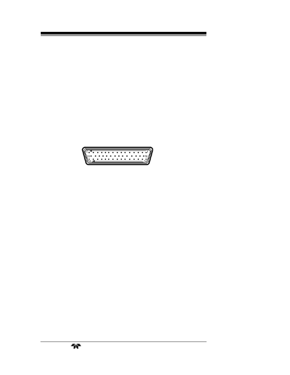
There are three 50-pin Equipment Interface Connectors installed on
the rear panel of the GC-Pro TCD. Figure 3-2 shows the pin layout of
the Equipment Interface connectors. The arrangement is shown as seen
when the viewer faces the rear panel of the analyzer. The pin numbers
for each input/output function are given where each function is
described in the paragraphs below.
Figure 3-2: Equipment Interface Connector Pin Arrangement
From top to bottom the signals handled by the individual connectors
are as follows:
Top connector:
Alarm relay connections
Middle connector: Analog output signals
Bottom connector: Standard connector for all additional
signals
See Section 3.3.2.9 for Pin-Out connections for each connector.
3.3.2.4
A
NALOG
O
UTPUT
There are four DC output signal pins—two pins per output. These
are found on the middle connector. For polarity, see Table 3-1. The
outputs are:
0–1 VDC % of Range:
Voltage rises linearly with increasing
concentration, from 0 V at 0
concentration to 1 V at full scale. (Full
scale = 100% of programmable range.)