Teledyne GC-Pro/FID - Gas Chromatograph User Manual
Page 39
GC-Pro FID
Installation
Teledyne
Analytical
Instruments
25
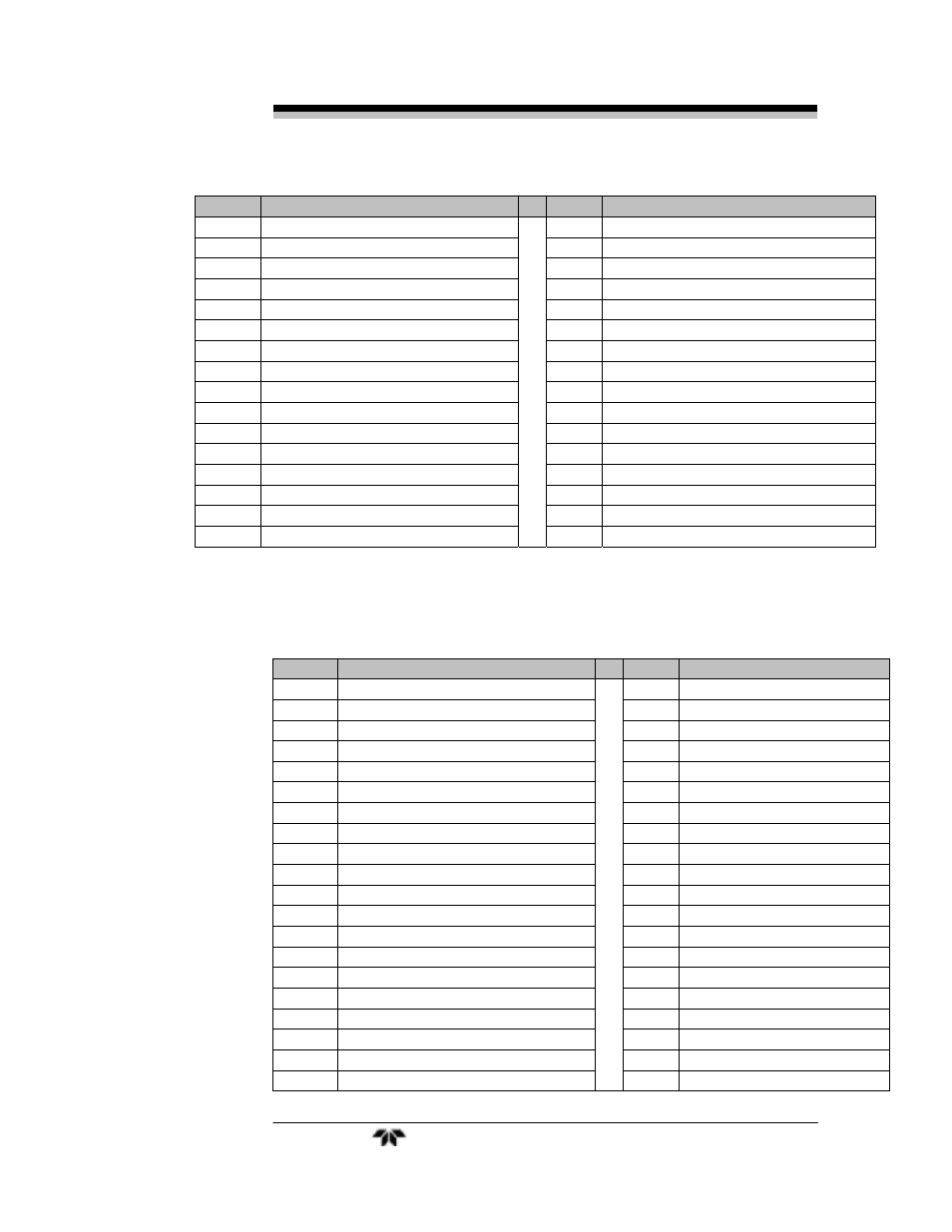
pin #
Description
pin #
Description
10 4-20 ma Out, Ch. # 7- RET
35
O2 sensor Hot Input #3 (NI)
11 4-20 ma Out, Ch. # 8- HOT
36
O2 sensor Return Input #3(NI)
12 4-20 ma Out, Ch. # 8- RET
37
Thermistor for O2 sensor #3 (NI)
13 4-20 ma Out, Ch. # 9- HOT
38
Thermistor for O2 sensor #3 (NI)
14 4-20 ma Out, Ch. # 9- RET
39
O2 sensor Hot Input #4 (NI)
15 4-20 ma Out, Ch. # 10- HOT
40
O2 sensor Return Input #4 (NI)
16 4-20 ma Out, Ch. # 10- RET
41
Thermistor for O2 sensor #4 (NI)
17 Analog Ground
42
Thermistor for O2 sensor #4 (NI)
18 Analog Ground
43
O2 sensor Hot Input #5 (NI)
19 0-1 vdc Out, Ch. # 3 - HOT
44
O2 sensor Return Input #5 (NI)
20 0-1 vdc Out, Ch. # 4 - HOT
45
Thermistor for O2 sensor #5 (NI)
21 Analog Ground
46
Thermistor for O2 sensor #5 (NI)
22 0-1 vdc Out, Ch. # 5 - HOT
47
O2 sensor Hot Input #6 (NI)
23 0-1 vdc Out, Ch. # 6 - HOT
48
O2 sensor Return Input #6 (NI)
24 Analog Ground
49
Thermistor for O2 sensor #6 (NI)
25 0-1 vdc Out, Ch. # 7 - HOT
50
Thermistor for O2 sensor #6 (NI)
(NI) = Not Implemented
Table 3-9: Pin out of Standard (Bottom) 50 pin D-Sub Connectors
pin #
Description
pin #
Description
1
26
2
27
3 + Output 4-20 ma - Channel 2
28 Alarm 1 C Contact
4 - Output 4-20 ma - Channel 2
29
5 + Output 4-20 ma – Channel 1
30
6 - Output 4-20 ma – Channel 1
31
7 - Output 0-1 v (Channel 1)
32 Exhaust Solenoid Hot
8 + Output 0-1 v (Channel 2)
33 Sample Solenoid Hot
9
34 Range 4 Contact/ not used
10 Remote Span +
35 Range 4 Contact/not used
11
36 Alarm 3 NC Contact
12 Remote Span -
37 Alarm 3 NO Contact
13
38 Range
1
Contact
14
39 Range
2
Contact
15
40 Calibration
Contact
16 Span Solenoid Return
41 Calibration Contact
17 Span Solenoid Hot
42 Alarm 2 NC Contact
18 Range 3 Contact
43 Alarm 2 NO Contact
19 Range 3 Contact
44 Alarm 2 C Contact
20 Alarm 3 C Contact
45 Alarm 1 NC Contact