Teledyne GC-Pro/FID - Gas Chromatograph User Manual
Page 23
GC-Pro FID
Operational Theory
Teledyne
Analytical
Instruments
9
2.3.1 Sample System
All components used to control the sample and supporting gases, as
well as the combustion portion of the detector cell, are located inside the
analyzer chassis. They are accessible by opening the front door of the
analyzer.
Adjustments are made using the appropriate control on the front
panel.
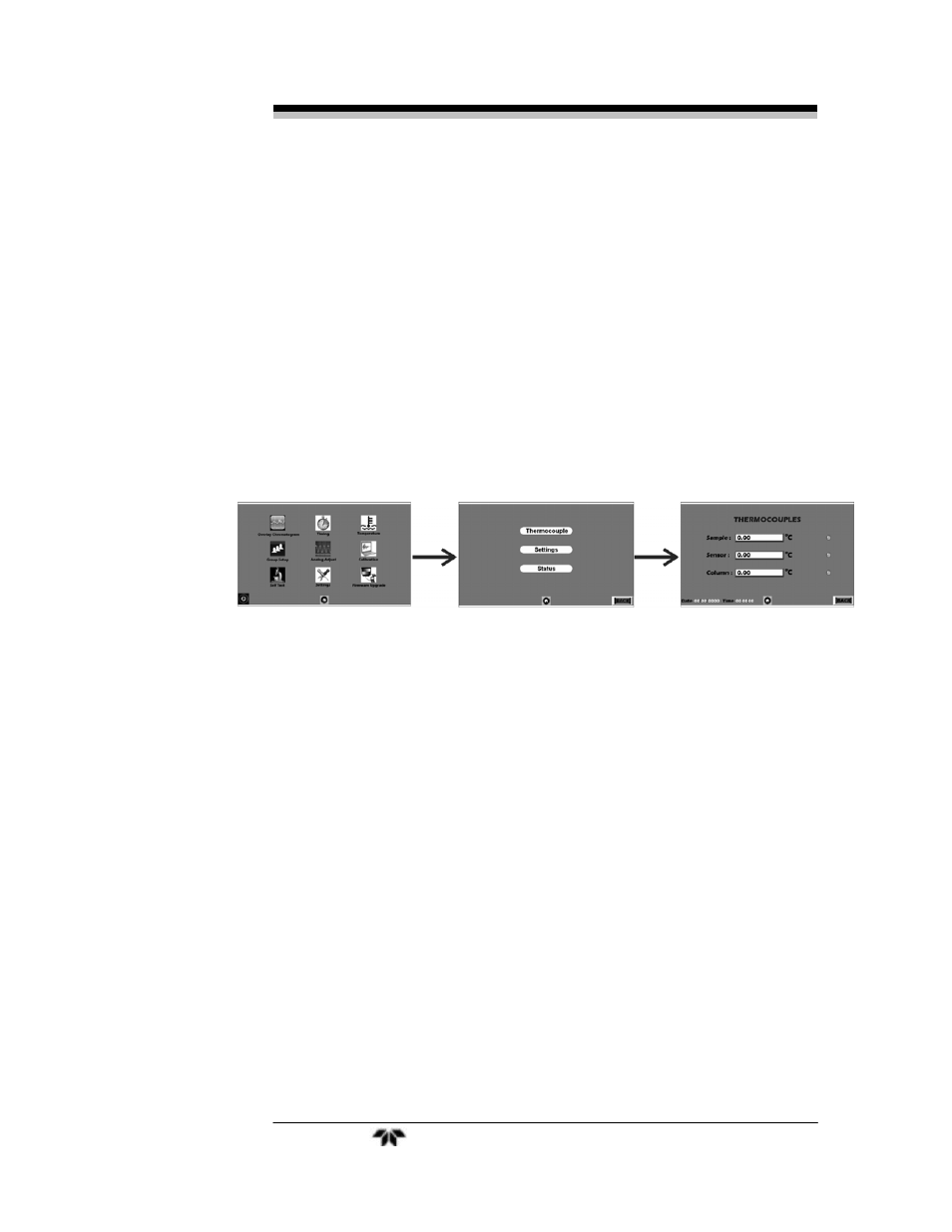
The analyzer contains three separate isothermal chambers
‘SAMPLE’, ‘FID’, and ‘COLUMN’ that are controlled by internal
temperature control PCBs. The temperature can be monitored and
controlled using the touch screen main menu item ‘Temperature’. See
Figure 2-1 and Section 4.7.7.
Figure 2-1: Internal Temperature Controller Screens
The sample chamber contains the 10-port GC switching valve and 2
sample loops. The ‘FID’ chamber contains the flame, pressure
regulators, pressure gauges and flow restrictors used by the FID
detector. The ‘COLUMN’ is housed in a separate ‘COLUMN’ enclosure
and maintained at a temperature of 70° C by its PID temperature
controller. The actual temperature setpoint for your instrument may be
different depending on the application. It is listed in the Addendum and
Testing Results section of Appendix C.
2.3.2 Gas Flow Control System
The analyzer is equipped with ports for the introduction of air, fuel,
carrier gas, span, and sample gas. It is imperative that these gases are
supplied at constant pressures using two stage stainless steel diaphragm
gas regulators. The recommended pressure range is 30 to 80 psig;
however, the span gas should be supplied at a pressure of 20 psig to the
restrictor fitting either on the optional auto calibration module or the
span inlet on the rear panel.