Teledyne 2020 - Explosion proof thermal conductivity analyzer User Manual
Page 31
Teledyne Analytical Instruments
Thermal Conductivity Analyzer
Installation 3
3-13
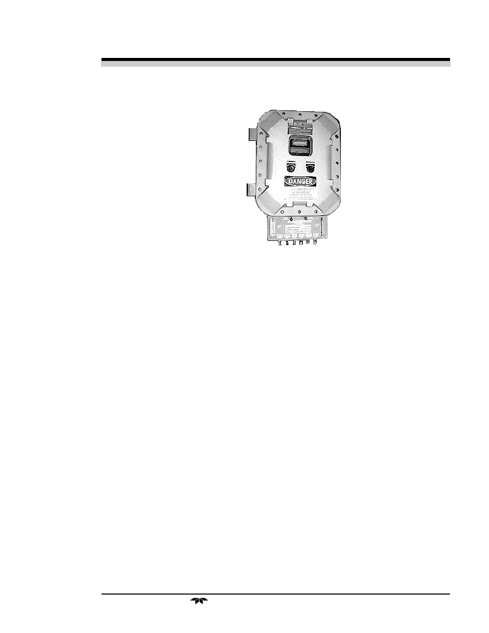
Figure 3-9: Front Panel with optional selector panel (as shown)
3.4.1 Sample System Design
Gas Connector and Selector Panels for specific applications are
available at additional cost . These panels are optional designed to substi-
tute a standard front panel.
For those customers wishing to incorporate their own sample system,
electronic input/output ports are provided on the electrical connection
board for the operation of solenoid valves under the complete control of
the Model 2020 electronics. See section 3.3. The recommended system
piping schematic is included among the drawings at the rear of the manual.
The unit is manufactured with
1
/
4
inch tubing and
1
/
8
NPT thread ports.
The customer must provide matching fittings.
For best results, use the recommended piping system. Select a
flowmeter that can resolve 0.08 scfh (40-50 cc/min) for the reference path
of the analyzer, and select a flowmeter that can resolve 0.3 scfh (150 cc/
min) for the sample path of the analyzer.
Note: The sample-line pressure regulator should be installed as
close to the sample point as possible to minimize sample-line
lag time.