Teledyne 2020 - Explosion proof thermal conductivity analyzer User Manual
Page 25
Teledyne Analytical Instruments
Thermal Conductivity Analyzer
Installation 3
3-7
Actuates when self test fails.
To reset a system alarm, call out the set up menue
by scroll keys. Use UP/DOWN key to select
STANDBY function. Turn off analyzer by pressing
ENTER key. Turn analyzer back on by selecting
any key. Set ESC key twice.
Further detail can be found in chapter 4, section 4-5.
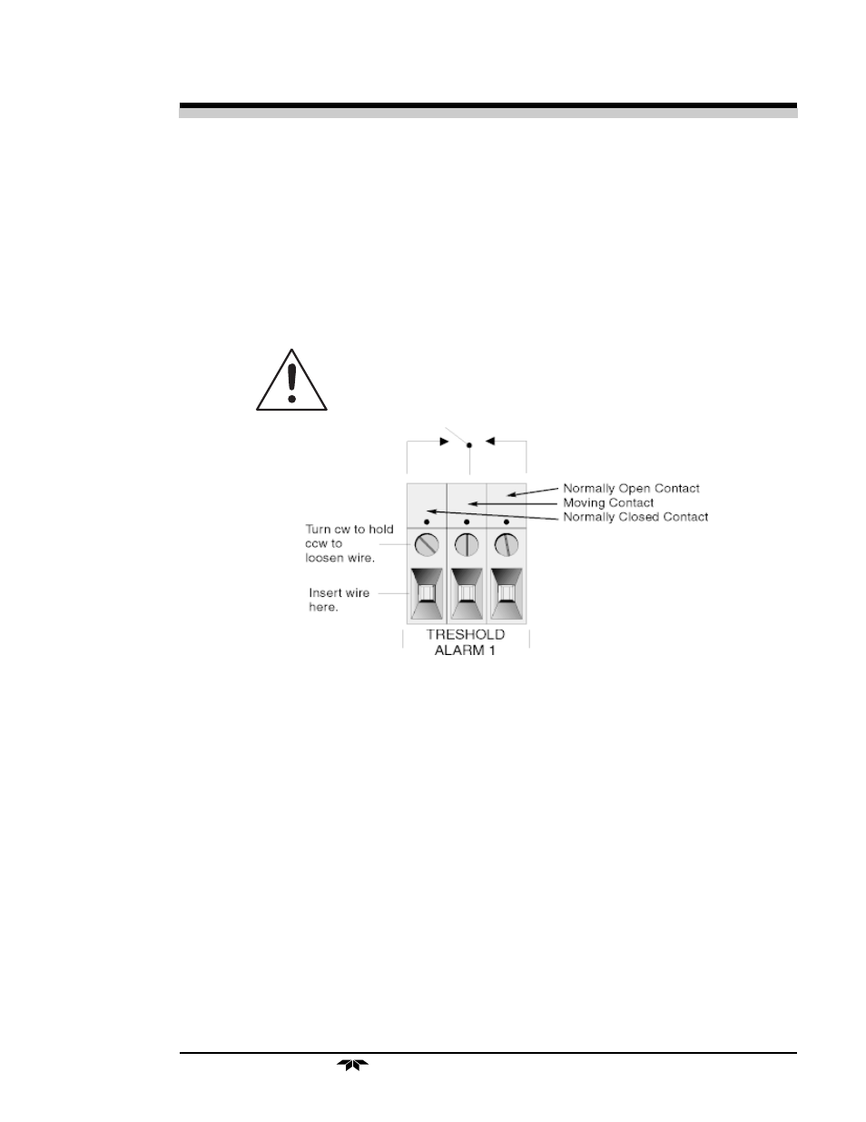
DANGEROUS VOLTAGES MAY STILL BE
PRESENT AT THIS TERMINALS EVEN IF POWER
TO THE INSTRUMENT IS REMOVED.
Figure 3-5: Types of Relay Contacts
3.3.6 Digital Remote Cal Inputs
Accept 0 V (off) or 24 V dc (on) inputs for remote control of calibra-
tion. (See Remote Calibration Protocol below.)
Zero:
Floating input. 5 to 24 V input across the + and – terminals
puts the analyzer into the
Zero
mode. Either side may be
grounded at the source of the signal. A synchronous signal
must open and close the external gas control valves appro-
priately. See 3.3.9 Remote Probe Connector. (With the –C
option, the internal valves operate automatically.)
Span:
Floating input. 5 to 24 V input across the + and – terminals
puts the analyzer into the
Span
mode. Either side may be
grounded at the source of the signal. A synchronous signal
must open and close the external gas control valves appro-