Teledyne 2010A - Split architecture thermal conductivity analyzer User Manual
Page 29
Teledyne Analytical Instruments
Thermal Conductivity Analyzer
Part I: Control Unit
Part I 3-
(Reset by pressing I/o button to remove power. Then
press I/o again and any other button EXCEPT Sys-
tem to resume.
Further detail can be found in chapter 4, section 4-5.
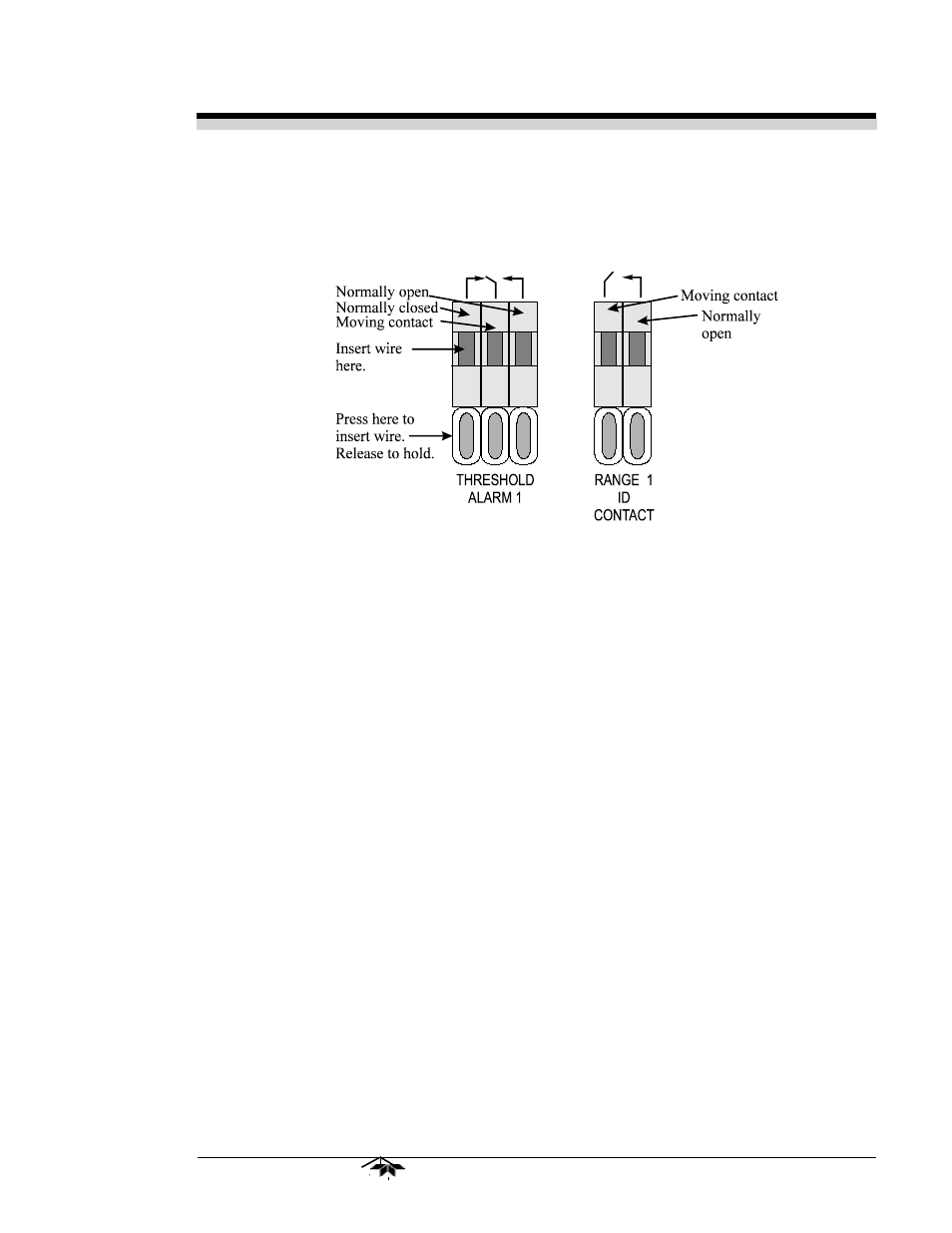
Figure 3-: Types of Relay Contacts
3.3.5 Digital Remote Cal Inputs
Accept 0 V (off) or 24
V dc (on) inputs for remote control of calibra-
tion. (See Remote Calibration Protocol below.)
Zero:
Floating input. 5 to 24 V input across the + and – terminals
puts the analyzer into the Zero mode. Either side may be
grounded at the source of the signal. A synchronous signal
must open and close the external gas control valves appro-
priately. See 3.3.9 Remote Probe Connector. (With the –C
option, the internal valves operate automatically.)
Span:
Floating input. 5 to 24 V input across the + and – terminals
puts the analyzer into the Span mode. Either side may be
grounded at the source of the signal. A synchronous signal
must open and close the external gas control valves appro-
priately. See 3.3.9 Remote Probe Connector. (With the –C
option, the internal valves operate automatically.)
Cal Contact: This relay contact is closed while analyzer is spanning
and/or zeroing. (See Remote Calibration Protocol below.)
Remote Calibration Protocol: To properly time the Digital Remote
Cal Inputs to the Model 2010A Analyzer, the customer's controller must
monitor the Cal Relay Contact.
When the contact is OPEN, the analyzer is analyzing, the Remote Cal
Inputs are being polled, and a zero or span command can be sent.