Teledyne 2010A - Split architecture thermal conductivity analyzer User Manual
Page 12
Teledyne Analytical Instruments
1- Part
1 Introduction
Model 2010A
• Alarms Set the alarm setpoints and attributes.
• Range Set up the user definable ranges for the instrument.
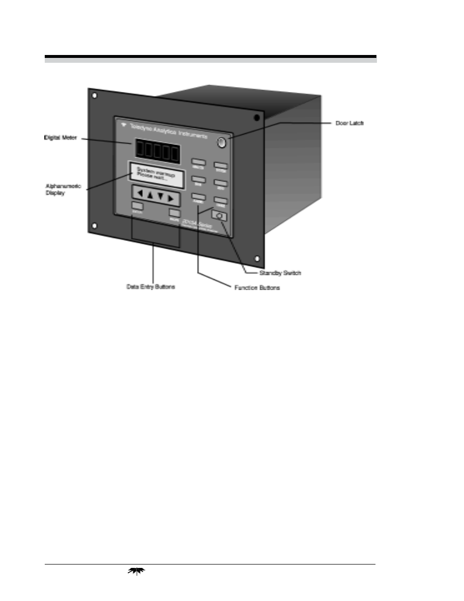
Data Entry Keys: Six touch-sensitive membrane switches are used to
input data to the instrument via the alphanumeric VFD (Vacuum Fluores-
cent Display) display:
• Left & Right Arrows Select between functions currently
displayed on the VFD screen.
• Up & Down Arrows
Increment or decrement values of
functions currently displayed.
• Enter Moves VFD on to the next screen in a series. If none
remains, returns to the Analyze screen.
• Escape Moves VFD back to the previous screen in a series. If
none remains, returns to the Analyze screen.
Digital Meter Display: The meter display is a VFD device that
produces large, bright, 7-segment numbers that are legible in any lighting.
It produces a continuous trace readout from 0-9999 ppm or a continuous
Figure 1-1: Model 010A Front Panel
- 1220 - Multipoint flammable gas and vapor detection system (50 pages)
- 212R - Thermal conductivity analyzer (28 pages)
- 235 - Thermal conductivity analyzer (38 pages)
- 275R - Portable turbine generator purge gas analyzer (21 pages)
- 2000A-EU - General purpose thermal conductivity analyzer (86 pages)
- 2000XTC - Thermal conductivity analyzer (40 pages)
- 2010B - Split architecture thermal conductivity analyzer (98 pages)
- 2020 - Explosion proof thermal conductivity analyzer (80 pages)
- 2120 - Trace Nitrogen in Argon Analyzer (66 pages)
- 2120XL - Trace Nitrogen Analyzer (85 pages)
- 2230R - Process Hydrogen Analyzer (26 pages)
- 2240 – Portable Handheld Hydrogen Leak Detector, 3rd generation (updated 1/31/11) (30 pages)
- 2240 - Portable Handheld Hydrogen Leak Detector, 3rd generation (revision 2/29/08) (40 pages)
- 2240 – Portable Handheld Hydrogen Leak Detector, 2nd generation (13 pages)
- 2750 - Portable turbine generator gas analzyer (40 pages)
- 300P - Percent oxygen analyzer (24 pages)
- 306WA - Analog trace oxygen analyzer (46 pages)
- 311 - Portable trace oxygen analyzer (19 pages)
- 311D - Portable trace oxygen analyzer with digital meter (18 pages)
- 311XL - Portable trace oxygen analyzer (18 pages)
- 316RA / RB / RAD / RBD - Oxygen analyzers (24 pages)
- 319R - Oxygen analyzer (23 pages)
- 320 Series - Portable oxygen detectors (24 pages)
- 326, 327 and 328 - Oxygen analyzers (45 pages)
- 329R - Oxygen analyzer (22 pages)
- 335 - Analog control room monitor for personnel safety (24 pages)
- 356WA - Analog trace oxygen analyzer (42 pages)
- 3000MA - Paramagnetic oxygen analyzer (63 pages)
- 3000MA - Paramagnetic oxygen analyzer Addendum (2 pages)
- 3000MB - Paramagnetic oxygen analyzer (59 pages)
- 3000PA - General purpose percent oxygen analyzer (69 pages)
- 3000PAEU - General purpose percent oxygen analyzer (78 pages)
- 3000PB - Bulkhead mount percent oxygen analyzer (82 pages)
- 3000TA - General purpose trace oxygen analyzer (75 pages)
- 3000TA-EU - General purpose trace oxygen analyzer (89 pages)
- 3000TA-XLEU - Trace oxygen analyzer (108 pages)
- 3000TB - Bulkhead mount trace oxygen analyzer (78 pages)
- 3000TB-XL - Trace oxygen analyzer (78 pages)
- 3000ZA - Trace oxygen analyzer (81 pages)
- 3000ZA-3X - Trace oxygen analyzer (72 pages)
- 3000ZA2G - Zirconium oxide analyzer (72 pages)
- 3000 Ultra Trace - PPB oxygen analyzer (72 pages)
- 3010MA - Paramagnetic oxygen analyzer, includes 0-100% range (88 pages)
- 3010MA – Paramagnetic oxygen analyzer, no 0-100% range – (superceded) (88 pages)