Liquid Controls SP2800 User Manual
Page 45
41
8-5 RS232 Card Wiring
This option has a subminiature D, 25 pin, fe-
male connector and is wired as a DCE (Data
Communications Equipment) device. If it is
connected to a DTE (Data Terminal Equip-
ment) device, the interconnect cable should
have wires 2 and 3 connected straight to the
same pins on each end.
If it is connected to another DCE device, Pins
2 and 3 must be crossed. This means that
the wire to pin 2 on one end goes to pin 3 on
the other end and the wire to pin 3 on one end
goes to pin 2 on the other end.
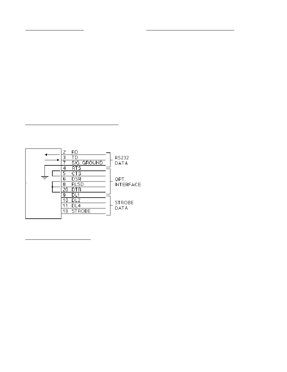
8-5.1 Wiring Diagram RS232 / Strobe (25 Pin
Connector)
8-5.2 RS232 Wiring Notes
The Batcher requires only three wires for
RS232 communication:
a) Pin 7 (Signal Ground)
b) Pin 2 (Receive Data)
c) Pin 3 (Transmit Data)
Other pins are jumped to simulate appropriate
responses required for some terminals.
a) Pin 4 (Request To Send), Pin 5 (Clear
To Send). Jumped internally to echo
back signals.
b) Pin 6 (Data Set Ready), Pin 8 (Re-
ceived Line Signal Detector), Pin 20
(Data Terminal Ready). Jumped inter-
nally to echo back signals.
8-6 RS422 Electrical Requirements
The input of the Batcher follows the standard
EIA high impedance minimum of 12 K Ohms.
When the 422+ (A) input is more positive than
the 422- (B) input by 0.2 V to 6 V, a "1" or
"Mark" condition is recognized. When the
422+ input is more negative than the 422- in-
put by 0.2 V to 6V, a "0" or "Space" is recog-
nized. Data is recognized by the polarity of
the voltage difference between the two lines.
Noise picked up in the line will make little dif-
ference since the noise is usually added to
each line and the voltage differential remains
the same. The output driver drives the trans-
mit lines to a differential of 2 to 6 V. It is
designed to handle loads up to 60 mA of sink
or source current and features positive and
negative current conditions. Since the RS422
is more immune to noise, cable links up to
1000 feet or more can be used. Because of
the high input impedance of RS422, line ter-
minating loads are recommended. For
hookup to a single unit, a 150 to 200 Ohm
resistor across Receive Data+ and Receive
Data(-), at the Batcher and at the remote
terminal is often sufficient. For multiple hook-
ups, other standard terminations should be
used. Note: Total loading should not be
greater than 90 Ohms.