Liquid Controls SP2800 User Manual
Page 34
30
SECTION 4 INPUTS
4-1 Digital Pulse Inputs (Terminal 4)
Digital Pulse Inputs: The input board is a
separate board that is plugged into the mother
board just behind the display. All digital
inputs are on the same board. There are four
dip switches on the board. The input condi-
tioning characteristics may be altered by
changing the dip switches. A valid pulse is
one which makes a transition from the off
state (low) to the on state (high): a positive
going edge. The off state is 0 - 1 VDC with
respect to Terminal 12 (Ground). The on
state is 3 - 30 VDC with respect to Terminal
12. The input impedance is 10 K ohms. At
30 VDC, the current draw will be 3 mA. This
should be the maximum current that the
Batcher will draw. Acceptable pulse width is
determined by the dip switch settings (See
Table 4-1 below).
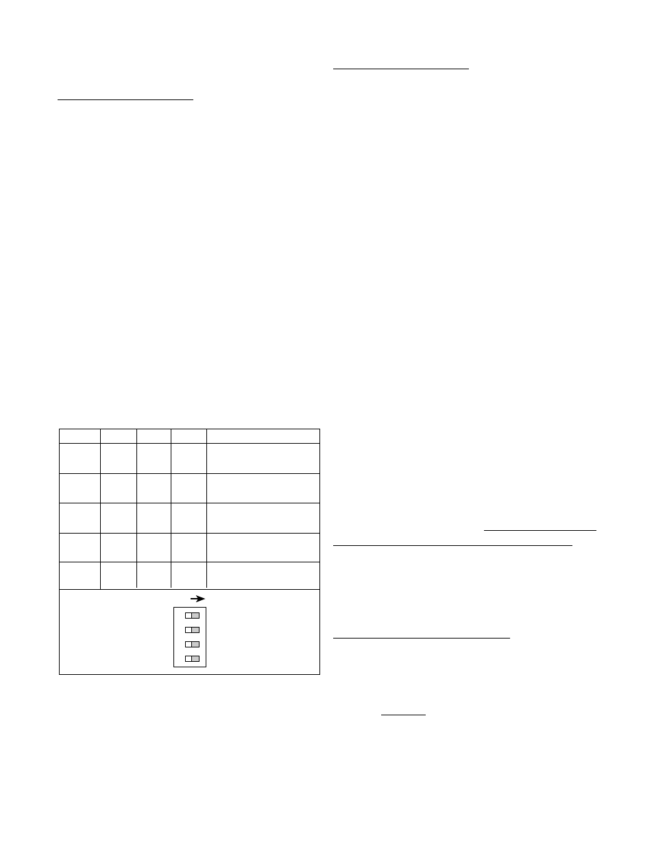
DIP SWITCH SETTINGS
Table 4-1
SW1
SW2
SW3
SW4
Conditioning
ON
ON
---
---
0-40 Hz
min. 12.5 msec on/off
ON
OFF
--- ---
0-400
Hz
min. 1.25 msec on/off
OFF
OFF
---
---
0-20000 Hz
min. 0.25 usec on/off
---
---
OFF
OFF
needs sourcing input
(drive input high)
---
---
OFF
ON
needs sinking input
(pull input low)
ON
S1
S2
S3
S4
4-1 Digital Pulse Inputs (continued)
4-1.1 STANDARD: High Impedance (Terminal
4).
Has a 10 K Ohm pull down resistor to ground
(Terminal 12) and must be driven high. Typi-
cal drivers include a contact closure from a 3-
30 VDC source (such as Terminal 13), a PNP
transistor (proximity switch or other device) or
an amplified signal from an inductive pickup.
Remember, the input signal must be refer-
enced to Terminal 12 of the Batcher. (See
Section 2-5, Fig. 2-2 Typical Digital Wiring
Connections)
4-1.2 High Impedance with pull-up (Terminal
4).
Has a 4.7 K Ohm pull up resistor to +5 VDC
and must be pulled low. Typical drivers in-
clude a contact closure to Ground (such as
Terminal 12), or an NPN transistor (proximity
switch or other device). Remember, the input
signal must be referenced to Terminal 12 of
the Batcher. (See Section 2-5, Fig. 2-2 Typi-
cal Digital Wiring Connections)
Idea: This input works well with TTL devices.
4-1.3 Reset Input (Terminal 5)
Identical to the Standard, High Impedance In-
put with one exception. The input speed is
fixed for a minimum pulse width of 5 msec.
Note: The reset input will not be changed to
a sourcing type of input even if the dip switch
is set for pull up or is changed to the pull up
settings.
4-2 Analog Inputs 5A - 5E, 6A (Terminal 4)
The input signal modules are mounted, just
like the Digital board, behind the display.
Analog inputs all use the same board, like-
wise so do the Analog-In/Out inputs. These
boards are not field modifiable (unlike the
Digital board). Each board is calibrated at the
factory for its particular input type.