4 bi-parting gates wiring - dual gate operators, Secondar y operator, Primar y operator – Controlled Products Systems Group 9100-080 User Manual
Page 35: Interconnection cable, Loop detectors 3-wire receiver, Secondary entrapment protection devices, Jumper wire, For bi-parting gates
9100-065-Z-3-13
33
ON
EXIT
LOOP
KEY SWITCH
4602
SW1
NC
NO
18
17
16
15
14
13
12
11
10
9
8
7
6
5
4
3
2
1
ON
EXIT
LOOP
KEY SWITCH
4602
SW1
NC
NO
18
17
16
15
14
13
12
11
10
9
8
7
6
5
4
3
2
1
3
2
1
Open Photo
Close Photo
Open Edge
Close Edge
Common
3
2
1
Open Photo
Close Photo
Open Edge
Close Edge
Common
UL 325
Terminal
UL 325
Terminal
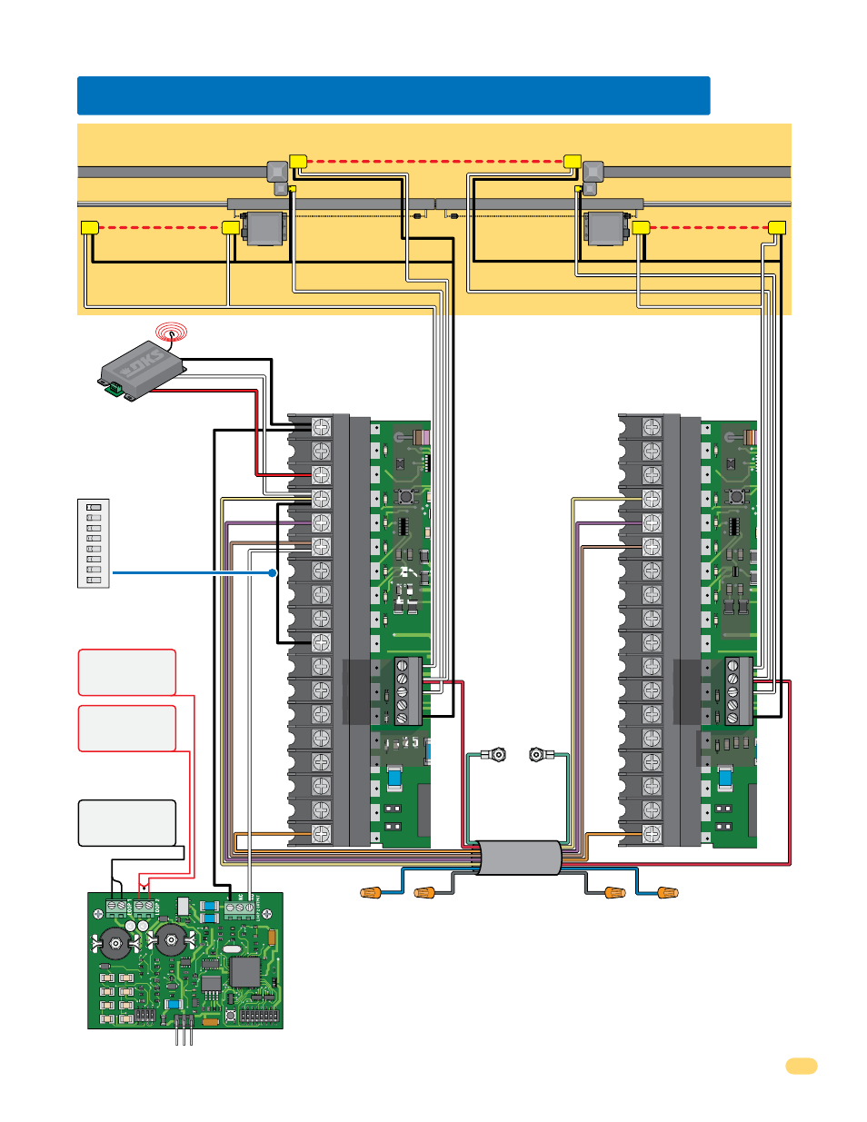
Interconnection Cable
Sold separately from DoorKing.
6 wires used (8 - 18 AWG wires total).
5.4 Bi-Parting Gates Wiring - Dual Gate Operators
Reverse loop lead-in
wires are wired in series.
When using Dual
Channel plug-in
loop detector.
Connect #4 to #10:
fully opens gates.
SW 2, switch 1
must be OFF.
Plug into Primary Operator Exit Loop Port
Dual Channel
9409
Automatic
Exit Loop
Reverse
Loop
Reverse
Loop
KEY SW
KEY SW
W
Secondar
y Operator
Yellow
24 Volt
Relay
Com
Purple
Brown
Yellow
Purple
Brown
Orange
Jumper Wire
Orange
Green to
primary
operator
chassis
ground.
Green to
secondary
operator
chassis
ground.
Red to Close Photo #2
Blue
Blue
Gray
Gray
Loop Lead-In Wires
Red to Close Photo #2
N.O.
Com
Loop Detectors
3-Wire Receiver
(Fully Opens Gates)
Secondary Entrapment Protection Devices
for Bi-Parting Gates
Jumper Wire
To Close Photo #2
To Close Photo #2
To Close Photo #2
To Open Edge #3
To Open Edge #3
To
Common #5
To
Common #5
To Open Photo #1
To Open Photo #1
Fence
Gate
Opening Non-Contact Sensor
Closing Non-Contact Sensor
Opening Contact Sensor
Opening Contact Sensor
Opening Non-Contact Sensor
Fence
250 mamp. max.
4-wire receiver wiring,
see page 31.
ON
1
2
3 4
5
6 7 8
SW 2
1
2
3
4
5
1
2
3
4
5
Gate
EY SWI
EY SW
WI
Primar
y Operator
•
Requires AC power to each operator.
•
Both operator DIP-switches must to be set.
•
Connect all control devices, auxiliary devices
and loops to the primary operator only.
•
Separate power source for
photo sensors (See page 26).
Secondary
Operator
Primary
Operator
Filler Post if necessary (See page 4 for more information).
Filler Post if necessary (See page 4 for more information).