2 control wiring for single/primary operator – Controlled Products Systems Group 9100-080 User Manual
Page 33
9100-065-Z-3-13
31
KEY SWITCH
4602
NC
NO
18
17
16
15
14
13
12
11
10
9
8
7
6
5
4
3
2
1
“Optional” REVERSE GATE for
Closing Direction Photo Sensors
Functions ONLY during gate closing cycle.
SW 2, switch 2: After photo sensor beam
gets obstructed:
OFF Setting - REVERSES GATE.
ON Setting - Stops gate then continues
closing when gate is clear (Same function
as UL 325 terminal #2).
Note: The ON setting is used to help prevent tailgating
but the photo sensor should be wired to the UL 325
terminal #2 when the “stop gate” function is desired,
see page 27 for more information.
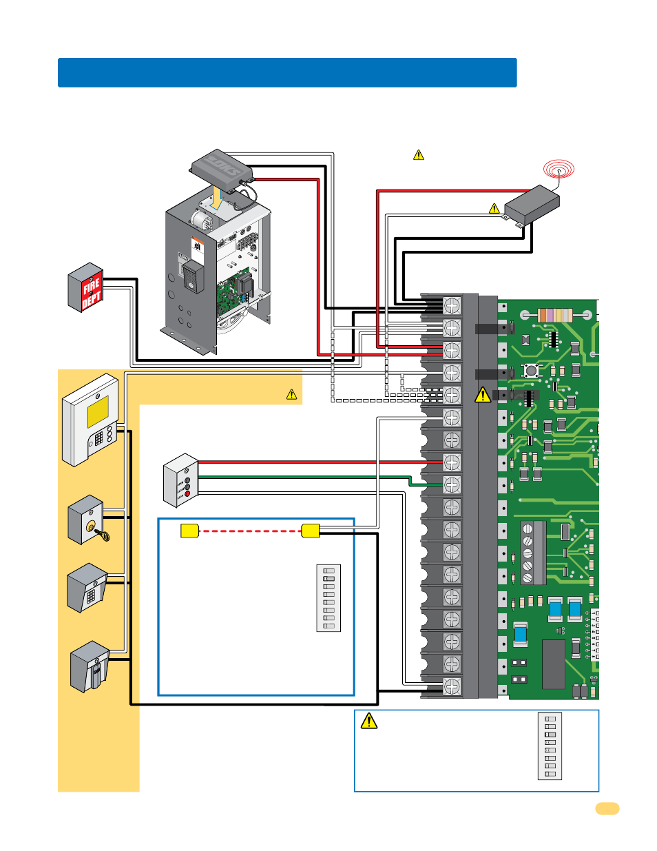
5.2 Control Wiring for Single/Primary Operator
ON
1
2
345678
SW 2
Red Full Open
Green Close
White Com
Key Switch
Stand-Alone
Keypad
Stand-Alone
Card Reader
Telephone
Entry
Fire Box
3-Button Control Station
DoorKing ONLY
Note:
All stand-alone and
telephone entry
devices must use a
separate power
source.
#4-Connected device fully opens gate.
#5-Connected device opens gate 14-feet.
#2-Fully opens gate.
Com
Com
Com
Relay -
#2 - Fully opens gate.
#5 - Opens gate 14-feet.
Relay N.O. - #2 - Fully opens gate.
#5 - Opens gate 14-feet.
250 mamp.
max.
3-Wire Radio
Receiver
ON
12
3
45678
SW 2
SW 2,
switch 3
must be
OFF.
Relay Com
24 Volt Com
24 Volt - 250 mamp. max.
4-Wire
Receiver
#5 Terminal Note (Single Operator Only):
Any opening device connected to terminal #5
will open the gate to the partial open 14-ft setting.
Secondary entrapment protection devices will also
open the gate to the partial open setting. If the
Inherent Reverse Sensor gets activated during the
close cycle, it will always fully open the gate.
24 volt
ON
ON
REVERSE
SE
NSITIVIT
Y
REV
ER
SE
LO
OP
EXIT
LO
OP
KEY
SWITC
H
DOOR
KI
NG
4602-01
0
SW
1
SW
2
OP
EN
TIM
ER
NC
1
2
3
4
5
NO
WA
RNI
NG
MOVI
NG
GA
TE
CAN
CA
US
E
Op
era
te g
ate
on
ly w
hen
ga
te a
rea
is i
n s
igh
t
and
free
of p
eop
le a
nd o
bstr
ucti
ons
.
Do
no
t all
ow
ch
ildre
n to
pla
y in
ga
te a
rea
or
ope
rate
ga
te.
Do
no
t stan
d in
gat
e p
ath
or
wal
k th
rou
gh
path
w
hile
ga
te is
mo
vin
g.
Re
ad
ow
ner
’s ma
nual
an
d s
afe
ty in
struc
tion
s.
SER
IOU
S IN
JUR
Y O
R D
EA
TH
CL
AS
S
CE
RT
IFIE
D
TO
CAN
/CS
A C2
2.2
NO.
24
7
CO
NF
OR
MS
TO
AN
SI/
VEHI
CU
LA
R G
AT
E O
PER
ATO
R
HP
533
82
MO
DE
L
SER
IAL
VO
LTS
PHA
SE
AM
PS
60 H
z
MA
X
GA
TE L
OA
D
DoorK
ing,
Inc
.,
Ingl
ew
oo
d,
CA
Full Open
Full Open
Partial Open
Important:
Controls intended for user activation must be located at least six (6) feet away from any moving part of the gate and where the user
is prevented from reaching over, under, around or through the gate to operate the controls.
Emergency access controls only accessible by authorized personnel (e.g., fire, police, EMS) may be placed at any location in the line-of-sight of
the gate.