3 loop detector wiring, Reverse loops, Automatic exit loop – Controlled Products Systems Group 9100-080 User Manual
Page 31: Doorking plug-in loop detectors
9100-065-Z-3-13
29
9410
Reverse
4 Ft. min. to avoid gate
movement inter
ference.
4 Ft. min. to avoid
reverse loop inter
ference.
4 Ft. min. to avoid gate
movement inter
ference.
Reverse
Automatic Exit
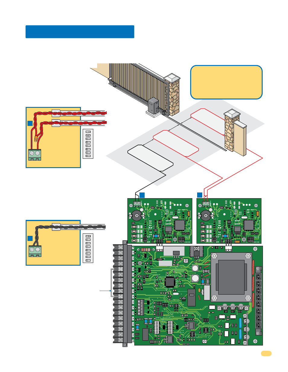
Note: Loop detector wiring is shown for
DoorKing plug-in loop detector P/N 9410-010
(Single Channel) only. If other loop detectors
are used, refer to the installation instructions
supplied with those detectors for wiring and
separate power instructions.
9410
Single Channel
Single Channel
4.3 Loop Detector Wiring
ON
ON
REVERSE
SENSITIVITY
REVERSE
LOOP
EXIT
LOOP
KEY SWITCH
DOORKING
4602-010
SW1
SW2
OPEN
TIMER
NC
1
2
3
4
5
NO
18
17
16
15
14
13
12
11
10
9
8
7
6
5
4
3
2
1
Loop Lead In Wires
Loop Lead In Wires
DoorKing
Plug-in
Loop Detectors
Note: See page 23,
SW 2, switch 2 for
reverse loop
options.
A
B
Reverse Loops
Reverse loops are placed on each
side of the gate to prevent the gate from
closing on a vehicle in the gate’s path. They will
reverse OR stop the cycling of the gate while a
vehicle is in or near the gate’s pathway.
To help protect the operator from accidentally closing on vehicles in the gate’s path, DoorKing highly recommends that loops
and loop detectors be installed. Loops are laid underneath, cut into asphalt or concrete driveways or buried beneath gravel and
earth driveways. A loop detection system will sense a vehicle like a metal detector and send a signal to the gate operator
preventing the gate from automatically opening or closing on a vehicle when it is in the gate’s path. DoorKing recommends that
a licensed installer perform this work.
Note: The plug-in exit loop detector can
be wired to partially open gate 14-Ft. if
SW 2, switch 1 is turned OFF. A jumper
wire must be connected from terminal
#10 to terminal #5 (See next page for
more information).
ON
1
2
345678
SW 2
ON
1
2
345678
SW 2
SW 2,
switch 1
must be
ON to fully
open gate
(Normal
function).
Reverse loop
lead-in wires are
twisted approx.
6 twists per foot
and are wired in
series.
A
LOOP 1
B
LOOP 1
PVC Conduit
Partial Open
PVC Conduit
DoorKing offers a free “Loop and
Loop-Detectors Information
Manual” PDF located at
Doorking’s web site for more
information.
www.dkaccess.com
Automatic Exit Loop
Automatically opens the gate for exiting vehicles
without having to use a transmitter or keypad. The
exit loop can be placed a minimum of 4 feet away
from the reverse loop or far enough away from the
gate so the gate has started or completely opened
by the time you drive up to it (Free exit).
Exit loop lead-in
wires are twisted
approx. 6 twists
per foot.