Controlled Products Systems Group 1601-080 User Manual
Page 28
1601-065-M-05-07
installation guide 29
accessory installation/reversing edge
.06/5*/($)"//&-
3&7&34*/(&%(&
1 2 3 4 5 6 7 8 9
10 11 12 13 14
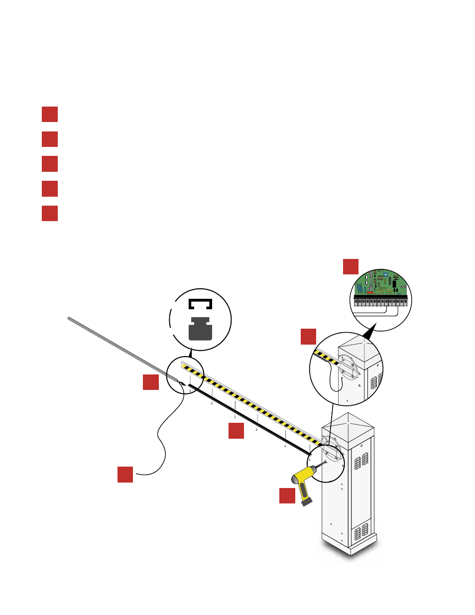
Turn operator power OFF and center and secure the 6-foot mounting channel
to the bottom of the barrier arm using ¾-inch wood screws (not supplied).
In addition to the electronic reversing device (ERD) an optional electric reversing edge (p/n 8080-016) maybe installed of-
fering additional protection to the arm, operator and obstruction.
Slide the reversing edge into the mounting channel
as shown.
Drill a ¼-inch hole on the side of the operator cabinet beneath the operator shaft
and install a grommet to protect the lead-in wire from any sharp metal edges.
Using wire ties (not supplied) secure the lead-in wire along the side of the
arm; leave a loop allowing the arm to rotate without obstruction.
Route the lead-in wire through the hole and connect to terminals 9
and 14 without interfering with any moving parts.
3
4
5
1
2
5
4
3
1
2
5