Electrical installation/ two-way lane application – Controlled Products Systems Group 1601-080 User Manual
Page 18
1601-065-M-05-07
installation guide 19
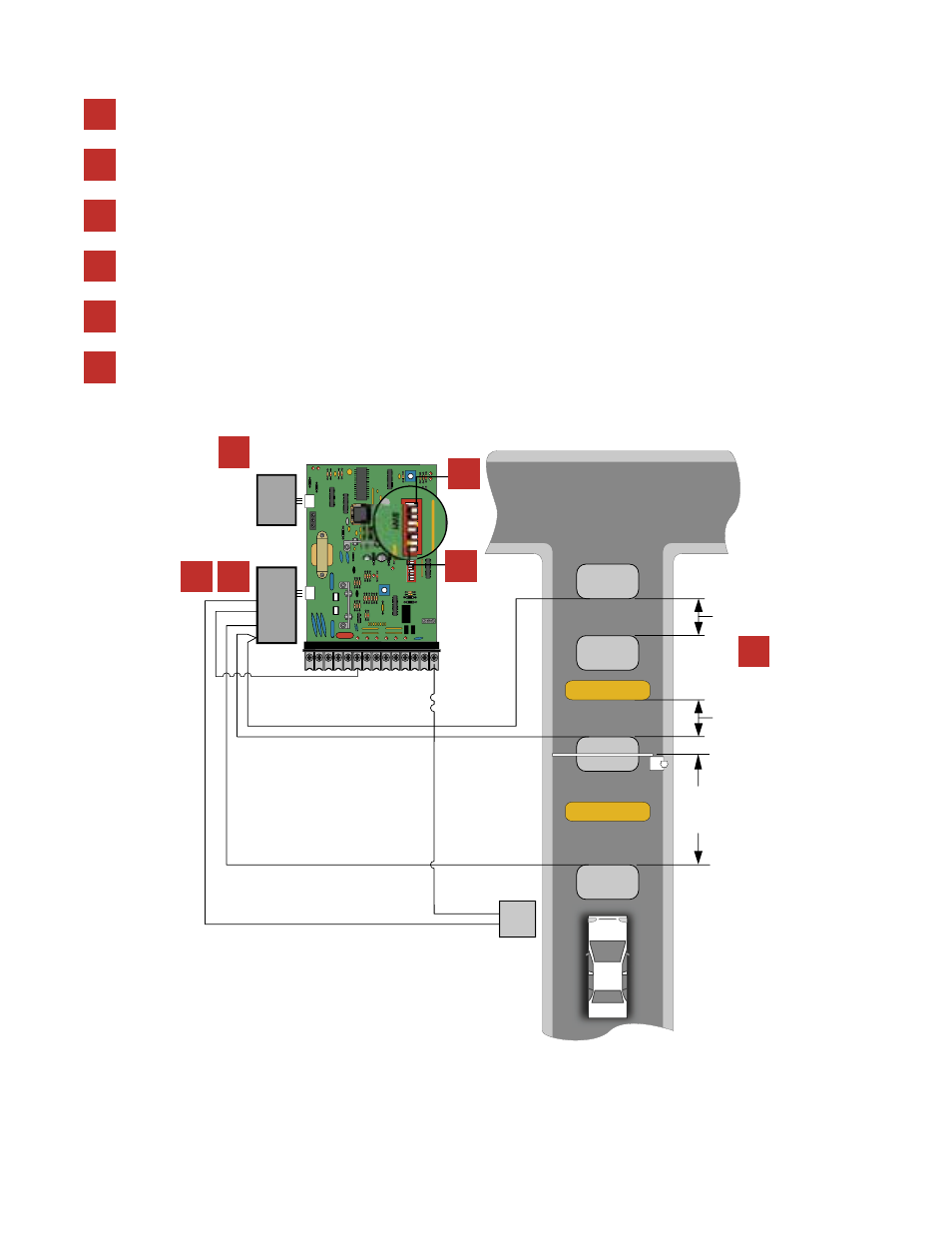
Spacing of the loops is critical when using this configuration. Be sure that the loops are spaced as shown in the diagram.
electrical installation/two-way lane application
$OWN
%XIT
1 2 3 4 5 6 7 8 9
10 11 12 13 14
SW2
1
2
3
4
5
6
7
8
1
2
3
4
5
6
7
8
3- DATA OUT
2- DATA IN
1- COMMON
TB 1
UP
PORT
9410
Loop
Detector
TB 2
TB 1
DOWN
PORT
9409
Loop
Detector
$OWN
!CCESS
#ONTROL
$EVICE
!RMING
/PTIONAL
COM
N.O.
-IN
1
2
3
4
5
6
7
8
ON
OFF
SW1
3PEED
3PEED
1
2
3
4
Plug a 9406 loop detector into the UP loop port on the 1601 circuit board and connect the EXIT loop to terminals TB-1.
Use a 9405 loop detector plugged into the DOWN port on the 1601 circuit board. Connect the DOWN loops, wired in series, to
terminals TB-1 and the ARMING loop to terminals TB-2.
If the optional arming loop is not used, use a 9406 detector plugged into the DOWN port on the 1601 circuit board and connect
the DOWN loops, wired in series, to terminals TB-1 on this detector.
The timer (SW-1, switch 7) should be OFF. The arm will rotate down after the vehicle clears the down loops.
SW-1, switch 4 must be ON.
5
6
6
1
2
3
5
4