Electrical installation/ exit lane application, Sw-1, switch 4 must be on – Controlled Products Systems Group 1601-080 User Manual
Page 16
1601-065-M-05-07
installation guide 17
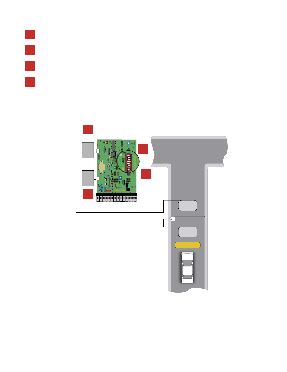
electrical installation/exit lane application
SW-1, switch 4 must be ON.
$OWN
%XIT
1 2 3 4 5 6 7 8 9
10 11 12 13 14
1
2
3
4
5
6
7
8
1
2
3
4
5
6
7
8
3- DATA OUT
2- DATA IN
1- COMMON
TB 1
TB 1
UP
PORT
DOWN
PORT
9406
Loop
Detector
9406
Loop
Detector
5
1
2
3
4
5
6
7
8
ON
OFF
SW1
3PEED
1
2
3
4
Use a 9406 detector plugged into the DOWN port on the 1601 circuit board and connect the DOWN loop to terminals TB-1 on this
detector.
Use a second 9406 detector plugged into the UP port on the 1601 circuit board and connect the EXIT loop to terminals TB-1 on
the detector.
The timer (SW-1, switch 7) should be OFF. The arm will rotate down after the vehicle clears the down loop.
1
2
3
4
This manual is related to the following products: