Electrical installation/ gate tracker wiring – Controlled Products Systems Group 1601-080 User Manual
Page 13
1601-065-M-05-07
14 installation
guide
electrical installation/gate tracker wiring
1 2 3 4 5 6 7 8 9
10 11 12 13 14
SW1
S
W2
1
2
3
4
5
6
7
8
1
2
3
4
5
6
7
8
3- DATA OUT
2- DATA IN
1- COMMON
"ELDEN
OR
#ONSOLIDATED
0
4O
3- DATA OUT
2- DATA IN
1- COMMON
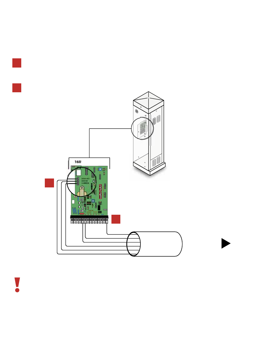
The operator will report status to the DoorKing Access Control System (Model 1803PC, 1815, 1817 or 1818) that is equipped with a Tracker
expansion board. This report includes operator cycle count, shorted inputs, loop detector problems, power interruptions, etc.
Maximum wire run for tracker board is 500 feet using Belden #9931 shielded cable or Consolidated #5324-CL
shielded cable. Float the shield at the tracker board. Do not connect the shield to the tracker board common.
Wire connection from the tracker board terminal P1-6 to the terminal 6 is optional if the barrier operator is not
to be activated by the tracker output relay.
For more detailed information on Gate Tracker™ and wiring to the Tracker expansion boards, refer to the
Tracker Installation and Wiring Manual, DoorKing P/N 2351-010.
1
2
1
Connect the wiring from the auxiliary terminal
strip located on the left side of the circuit board
to the Gate Tracker™.
Connect the wiring from terminals 5, 6 and 14
on the main terminal strip to the Gate Tracker™.
2