Settings/ magnetic limit – Controlled Products Systems Group 1601-080 User Manual
Page 24
1601-065-M-05-07
installation guide 25
settings/magnetic limit
1 2 3 4 5 6 7 8 9 10 11 12 13 14
SW1
SW2
1
2
3
4
5
6
7
8
1
2
3
4
5
6
7
8
ON
POWER
OFF
AUTO
DOWN
UP
1
2
3
4
5
6
7
8
ON
OFF
SW1
6 7 8 9 10 11 12 13 14
ON
POWER
OFF
AUTO
DOWN
UP
8 9
1 12 1
3,)$% !$*534
SW1
SW2
1
2
3
4
5
6
7
1
2
3
4
5
6
7
8
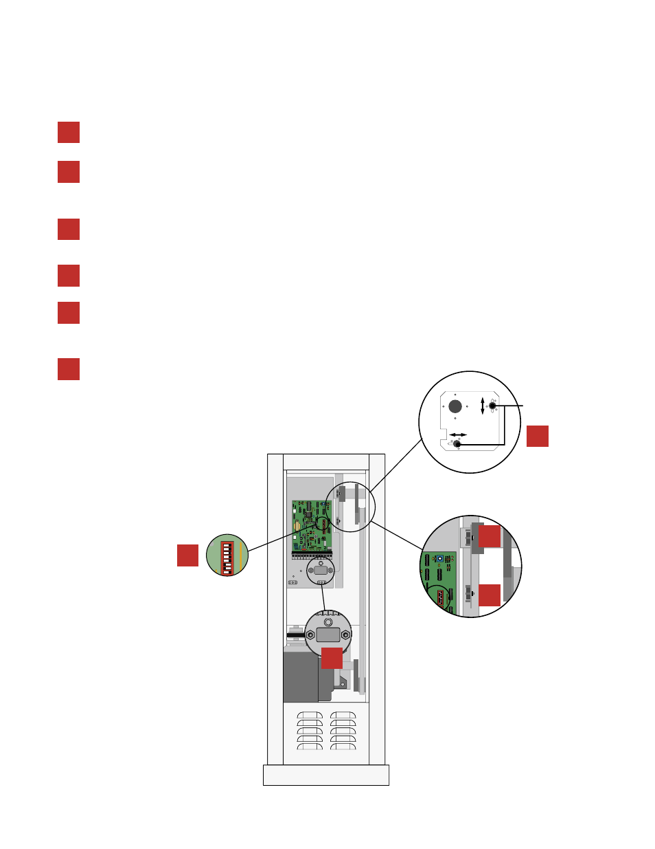
MAGNETIC LIMIT
ADJUSTMENT
The operator has been preset at the factory to rotate 90° no adjustments are necessary when used in a normal setup. Follow the steps
below to adjust the barrier arm rotation.
Check the shaft rotation by activating the UP input toggle
switch. NOTE: To prevent possible damage to the opera-
tor or barrier arms, remove any obstructions during ini-
tial checks.
Turn the operator power OFF at the breaker panel.
Remove the plastic circuit board cover. Set SW1 DIP-switch 3 to the
ON position. This changes the rotation of the gearbox from 360° to
180°, and allows the magnetic limits to stop the rotation at less than
180° if necessary, causing the arm to rotate less than 90°.
Loosen the nuts and adjust the rotation by sliding the magnets,
NOTE: sliding the magnets towards each other shortens the
rotation; the maximum rotation of the output shaft is 90°.
Tighten the nuts before turning the ON the operator at the
breaker panel.
3
2
1
4
5
6
Repeat steps 1 through 5 until the desired rotation
is achieved.
2
3
3
4
5