Settings/ control board, Dip switches, Auto close timer – Controlled Products Systems Group 1601-080 User Manual
Page 23: Relay 1 contact, Arm relay contacts, Power led, Limit led, Tracker activity led, Gate operator data terminal
1601-065-M-05-07
24 installation
guide
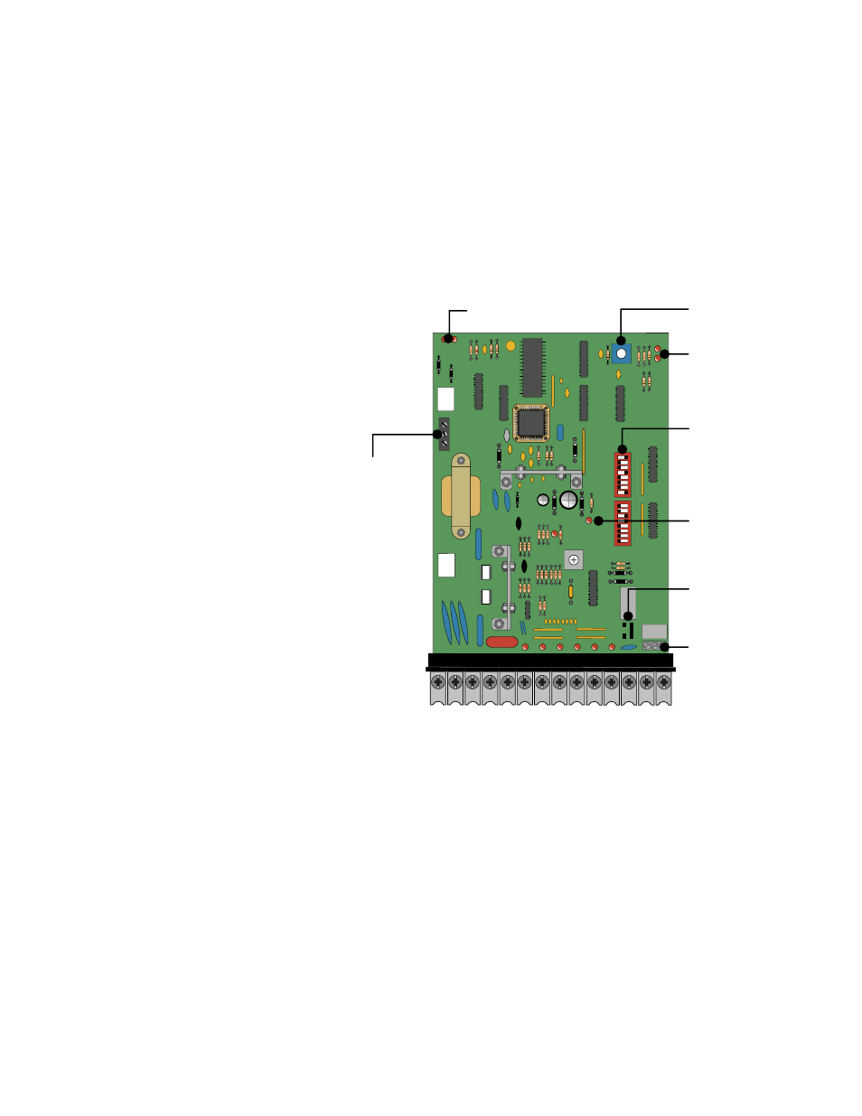
settings/control board
Settings and adjustments should be made after installation and wiring to the operator(s) is complete. Power must be shut-off before
programming switches on the circuit board are changed and turned back on for the new setting to take effect.
1 2 3 4 5 6 7 8 9
10 11 12 13 14
SW1
S
W2
1
2
3
4
5
6
7
8
1
2
3
4
5
6
7
8
1. DIP SWITCHES
- Turn OFF/ON operating
features and modes.
2. AUTO CLOSE TIMER
- Adjust from one (1)
second to (when set to full counter clock-wise)
to approxamately 60 seconds (when set to full
clock-wise).
3. RELAY 1 CONTACT
- (terminals 12-13)
can be set for Normally Open (NO) or Normally
Closed (NC) operation by placing the relay
shorting bar on the NO or NC pins respectively.
Relay activation is dependant on setting of
SW1, switch 5.
4. ARM RELAY CONTACTS
- (C – NC – NO)
This relay can be used for a variety of purposes
and is typically used to signal when the arm is
up or down.
5. POWER LED
- Indicates that low voltage
power is applied to the circuit board. The input
LEDs should be OFF and will only illuminate
when the input is activated.
6. LIMIT LED
- On when the arm is in the
respective position.
7. TRACKER ACTIVITY LED
- See page 14.
An automatic sensor system that senses entrap-
ment of a solid object and is incorporated as a
permanent and integral part of the operator.
8. GATE OPERATOR DATA TERMINAL
- Operator status reporting; cycle count, shorted
inputs, loop detector problems, power interrup-
tions, etc.
DIP
SWITCHES
AUTO CLOSE
TIMER
ARM RELAY
CONTACTS
RELAY 1
CONTACT
POWER
LED
LIMIT LED
TRACKER ACTIVITY LED
GATE OPERATOR
DATA TERMINAL