Option d - mount installation: can-am atvs – Kolpin 10-0520 X-Factor Plow User Manual
Page 18
18
© 2011 Kolpin Outdoors Inc.
OPTION D - MOUNT INSTALLATION: CAN-AM ATVs
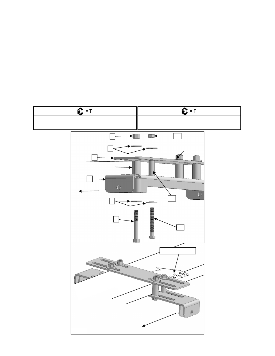
1. Position the Forward Mount Weldment, Item #1, under the frame tube behind the a-arms and under the brake cylinder bracket
extrusion as shown in Illustration 13.
2. Position the Back Plate, Item #2, on top of the frame tube and brake cylinder bracket as shown in Illustration 13.
3. IMPORTANT: Insert spacer, Item #10 at the left rear mount channel and brake cylinder bracket extrusion. Loosely fasten the
spacer, mount weldment and extrusion with the bolt, washers and locknut Items #11, #5 and #12. Do not torque fasteners at this
time.
4. Place spacers, Item #7, between the remaining mount and back plate locations. Loosely fasten the mount and back plate using
bolts, washers and locknuts, Items #3, #5 and #6. Do not torque fasteners at this time.
5. Once the final mount position has been determined, position fasteners to the frame tube walls as close as possible and torque to
specification.
Item #3 FASTENER TORQUE:
30 ft. lbs. (41 Nm)
Item #11 FASTENER TORQUE:
19 ft. lbs. (25.7 Nm)
ILL. 4
ATV FRONT
Bracket Extrusion
2
CAN-AM FRAME
SECTION VIEW
ATV FRONT
1
11
5
Bracket Extrusion
10
12
3
6
5
18