Hach-Lange PHOSPHAX sigma Basic User Manual User Manual
Page 92
English 92
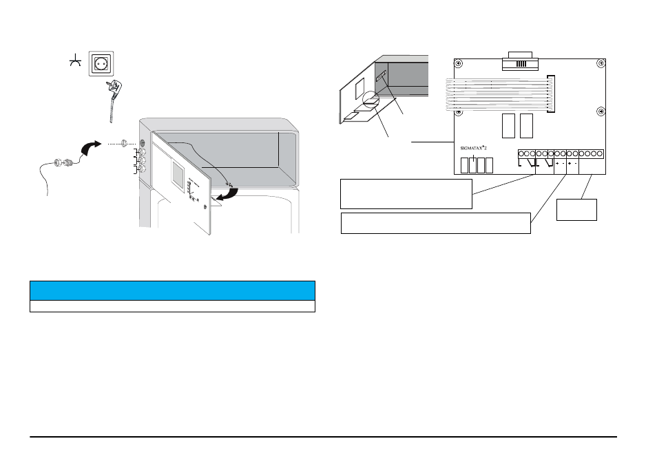
Figure 6 Routing of optical-fiber cable SIGMATAX 2 and signal lines
Terminal assignment — for current outputs and
limit-value contacts
Figure 7 View of the terminal board
In order to connect the transmission lines for current
output, limit-value contacts and bus interface, the following
work steps are required:
1.
Disconnect device from the mains supply.
2.
Open device door.
3.
Loosen the knurled screw at the top right and swivel the front panel
out forwards. The connections are located on the right on the
terminal board.
4.
Loosen the PG screw connection for the corresponding connection
cable and remove the blanking disc.
5.
Plug the cable through the screw connection into the device and
route forwards to the connection terminals.
6.
Plug cable ends into the corresponding connection terminals (wire
thickness maximum 1.5 mm
2
). The assignment of the connection
terminals is seen from
the view of the terminal board.
N O T I C E
Only shielded lines may be connected!
Optical-fiber cable from
SIGMATAX 2
Loosen
knurled screw
Front panel
Current output 1
Current output 2
Limit-value contacts
Interface
Power plug
Socket with
ground contact
A B A B
1 1 2 2
1
2
3
4
5
6
7
8
9
10
11
12 13 14
RS 485
32 23 32 23
Relay 1 Relay 2 Current 1 Current2
Current I = current output 1 (submenu (+SPECIAL P) or (+CURRENT 1))
Current II = current output 2 (submenu (+SPECIAL OP) or (+CURRENT 2))
Terminals for
shielding
Terminal board
Relay I = relay-min (lower limit-value contact)
Relay II = relay-max (upper limit-value contact)
(Figure shows relays in idle state.)
Interface:
bus-capable