Installation, Fluid installation – Burkert Type 8640 User Manual
Page 12
12
Installation
Version
4-fold
8-fold
12-fold
16-fold
24-fold
Feature
–
–
–
–
on request
M
111
±0.4
155
±0.4
199
±0.4
243
±0.4
331
±0.4
N1
114
±0.4
54
±0.3
68
±0.3
123
±0.4
66
±0.3
N2
–
158
±0.4
202
±0.4
246
±0.4
200
±0.4
N3
–
–
–
–
334
±0.4
N4
–
–
–
–
–
O
(Number of
bores)
6
8
8
10
12
G
148
192
236
280
368
Tab. 1: Dimensions of the flange images for AirLINE Quick.
7. INSTALLATION
7.1. Fluid Installation
DANGER!
Risk of injury from high pressure in the equipment!
• Before loosening lines or valves, turn off the pressure and vent
the lines.
• Design the connections with the largest possible volume.
• Close the open connections not required with lock screws.
• The connections for the pilot control exhaust air (x) must not be
sealed.
• Check correct assignment of the connections 1 and 3 or 5. They
may by no means be interchanged.
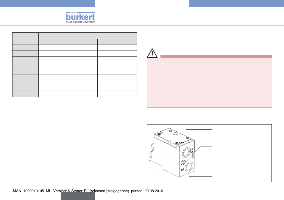
7.1.1. Pneumatic connections - feed
Pressure supply connection P/1
Exhaust air R/3, S/5
X channel:
Standard version:
Deaeration of the control valves
Control assist air version:
P connection for control valves
Fig. 8:
Pneumatic connections
english
Type 8640