Removal, Electrical control unit – Burkert Type 2300 User Manual
Page 28
28
Installation
8.4.1. Connection of the control medium
→
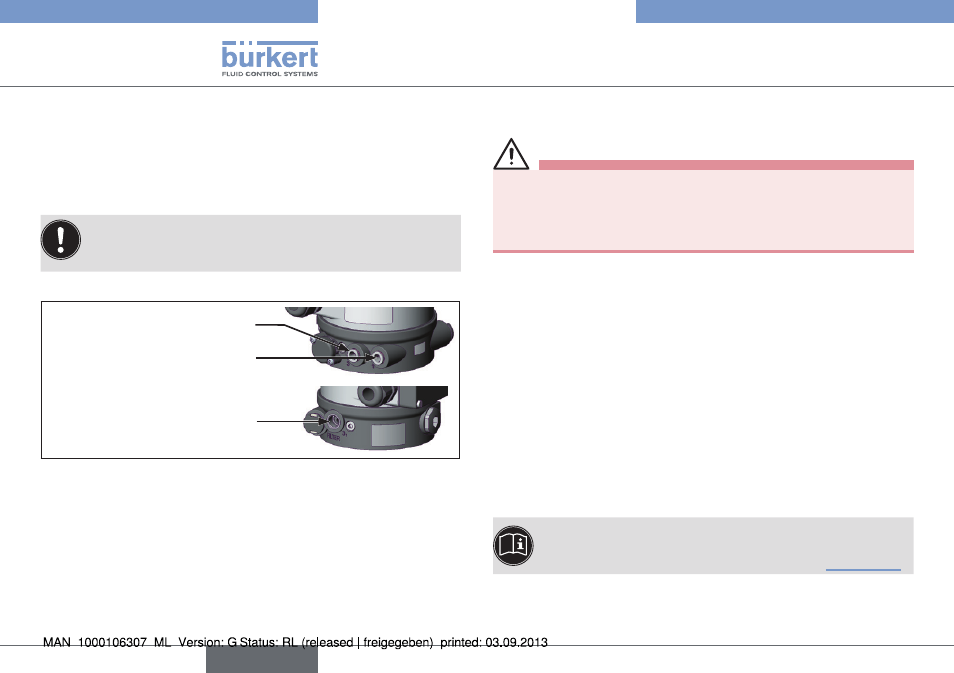
Connect the control medium to the pilot air port (1)
(3 – 7 bar; instrument air, free of oil, water and dust).
→
Fit the exhaust line or a silencer to the exhaust air port (3) and, if
available, to the exhaust air port (3.1).
If used in an aggressive environment, we recommend
conveying all free pneumatic connections into a neutral
atmosphere with the aid of a pneumatic hose.
Pilot air port
Exhaust air port
Additional exhaust air port only
with pilot-operated control
system for high air output
(actuator size ø 130)
1
3
3.1
Fig. 23: Pneumatic connection
Control air hose:
6/4 mm or 1/4" pilot air hoses can be used.
A pilot air port via G 1/8 thread is available as an option.
8.5.
Removal
DANGER!
Risk of injury from discharge of medium and pressure!
It is dangerous to remove a device which is under pressure due to
the sudden release of pressure or discharge of medium.
• Before removing a device, switch off the pressure and vent the lines.
Procedure:
→
Loosen the pneumatic connection.
→
Remove the device.
9.
ELECTRICAL CONTROL UNIT
The valve Type 2300 can be combined with following control units:
• Type 8692
Positioner
• Type 8694
Positioner
• Type 8696
Positioner
• Type 8693
Process controller
The electrical connection of the pilot valve or the control
unit is described in the respective operating instructions for
the pilot valve/control unit in the chapter titled “Installation”.
english
Type 2300