Brooks, Model 5850e – Brooks Instrument 5850E User Manual
Page 39
4-7
Section 4 Maintenance &
Troubleshooting
Installation and Operation Manual
X-TMF-5850E-MFC-eng
Part Number: 541B102AAG
September, 2009
Brooks
®
Model 5850E
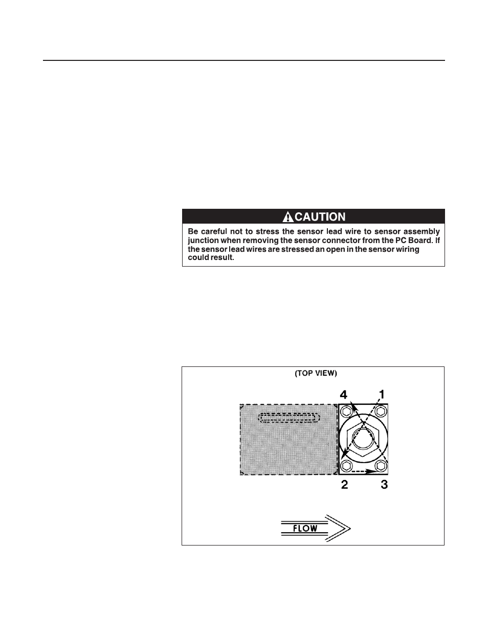
Figure 4-1 Torque Sequence for the Valve Retainer Plate
6. Remove and note the position of the valve spring spacers (10), which
may be located above and/or below the lower guide spring (8). Remove
the preload spacer spring (33)(NO Valve).
7. Unscrew the orifice (12) from the flow controller body(14).
8. Carefully unscrew the valve seat (11) from the plunger assembly (7)(NC
Valve) or the plunger assembly (31,32,35)(NO Valve).
Note the position and number of spacers (9) that are stacked on the
threaded end of the valve seat.
9. Remove the three screws (20) attaching the electronics cover. Remove
the electronics cover (23).
10.Unplug the sensor connector from the PC Board. Remove the two
screws securing the bracket (24) and PC Board (15). Remove the
bracket and PC Board.
11.Remove the two screws (18) and washers (19) securing the sensor
assembly (16). Remove the sensor assembly.