Brooks, Model 5850e – Brooks Instrument 5850E User Manual
Page 29
Brooks
®
Model 5850E
3-9
Section 3 Operation
Installation and Operation Manual
X-TMF-5850E-MFC-eng
Part Number: 541B102AHG
September, 2009
Example:
Controller error = 0.7%
Measured TP2 voltage = -0.567 Volts
TP2 correction = 0.7 x 0.450 = 0.315 Volts
New TP2 correction = 0.315 + (-0.567) = -0.252 Volts
Adjust the linearity potentiometer for an output equal to the new TP2
voltage and then repeat Steps “f,” “g” and “h.”
Note: The voltage at TP2 can range from -10 to +3 Volts. It is recom-
mended, however, that this voltage stay between -2.5 and +2.5 Volts for
proper operation. If the recommended voltage range is exceeded, the
desired accuracy and/or signal stability may not be achieved. If one of
the limits is reached, check the restrictor sizing (refer to Section 4-7).
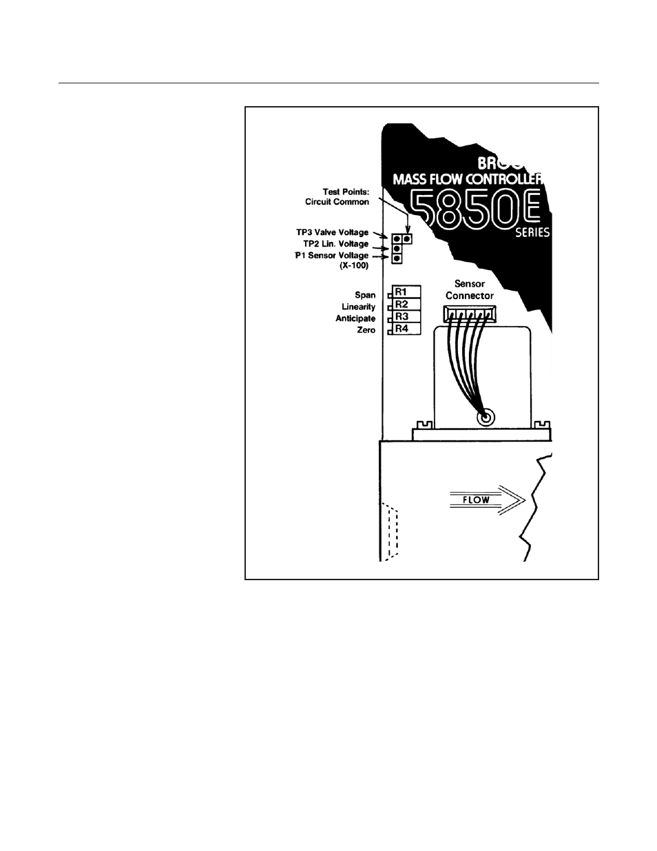
Figure 3-6 Adjustment Potentiometer Location
- QMBC (52 pages)
- SolidSense II (28 pages)
- SLA7810/20 (36 pages)
- SLA5810/20 (50 pages)
- SLA5840 (46 pages)
- SLA7840 (40 pages)
- 5866E (65 pages)
- IPS122 2 Indicating Pressure Switches" (18 pages)
- IPT122 2 Indicating Pressure Transmitters" (22 pages)
- 8601 (20 pages)
- PTI Metal Seal Mass Flow Controller w/Real-Time Flow Error Detection & Advanced Diagnostics (82 pages)
- SLA5800 Series (76 pages)
- 5800S Series (50 pages)
- 4800 Series (50 pages)
- 5850EM (74 pages)
- 5851EM (62 pages)
- 5851E (64 pages)
- 5860E (46 pages)
- 5861E (44 pages)
- 5850i (62 pages)
- 5851i (62 pages)
- 5860i (48 pages)
- 5861i (48 pages)
- 5881/91 (40 pages)
- GF40 (78 pages)
- SLAMf Series (76 pages)
- Mfi Series (82 pages)
- 0254 (124 pages)
- 0260 (14 pages)
- CMC Series (36 pages)
- XacTorr CMX45 (64 pages)
- MT3809G (78 pages)
- MT3809E (72 pages)
- MT3810 (66 pages)
- 3600 Series (56 pages)
- 3750 (64 pages)
- Control Valve (16 pages)
- GT1000 (52 pages)
- 1100 Series (52 pages)
- 1307 (18 pages)
- 1358 (44 pages)
- 1350 (46 pages)
- 1250 (2 pages)
- FC8800 Series (48 pages)